
Binocular case

a protective carrying case and optical instrument technology, applied in the direction of damagable goods packaging, transportation and packaging, packaging types of goods, etc., can solve the problems of lack of protection, hinder the accessibility of instruments, and storage does not permit easy access, so as to facilitate use, facilitate access, and facilitate the effect of us

Inactive Publication Date: 2012-03-13
CARSON OPTICAL
View PDF22 Cites 14 Cited by
  • Summary
  • Abstract
  • Description
  • Claims
  • Application Information

AI Technical Summary

Benefits of technology

[0007]For example, it is objectives of the present invention to provide an improved protective carrying case for optical instruments, more specifically binoculars, that adequately protects the instrument and does not hinder the accessibility of the instrument. Said protective carrying case is less complicated, easier to use, quiet, and generally more desirable and versatile than prior art constructions.
[0008]Another object of the present invention is the additional features of easy attachment and detachment to and from the optical instrument.
[0009]Yet another object of the invention would be to provide a case that is lightweight, durable, inexpensive and attractive.
[0013]The protective carrying case should protect the lenses, body, tube, adjustment knobs and attachments of the instrument. Such a case should provide protection against rain, snow, dust, twigs and the like. The case should also prevent damage if the instrument is hit against a foreign object. Moreover, the case should be quick and easy to open allowing use of the instrument while remaining attached to the case, thereby preventing loss or droppage of the case.

Problems solved by technology

If game or wildlife is sighted or if a need otherwise arises to have immediate access to the binoculars, however, such storage does not permit ready access.
However, these storage devices often either lack sufficient protection or hinder the accessibility of the instrument.
Heretofore a full protective carrying case designed for quick, quiet and easy use in the field, while remaining conveniently attached to the instrument has not been available.

Method used


Image

  • Binocular case
  • Binocular case
  • Binocular case

Examples


Embodiment Construction

[0026]Reference is now made to the Figures, which illustrate a protective carrying case, generally indicated at 10, constructed in accordance with preferred embodiments of the present invention. Prior to discussing the specifics, however, general overviews, features and advantages thereof shall be discussed.

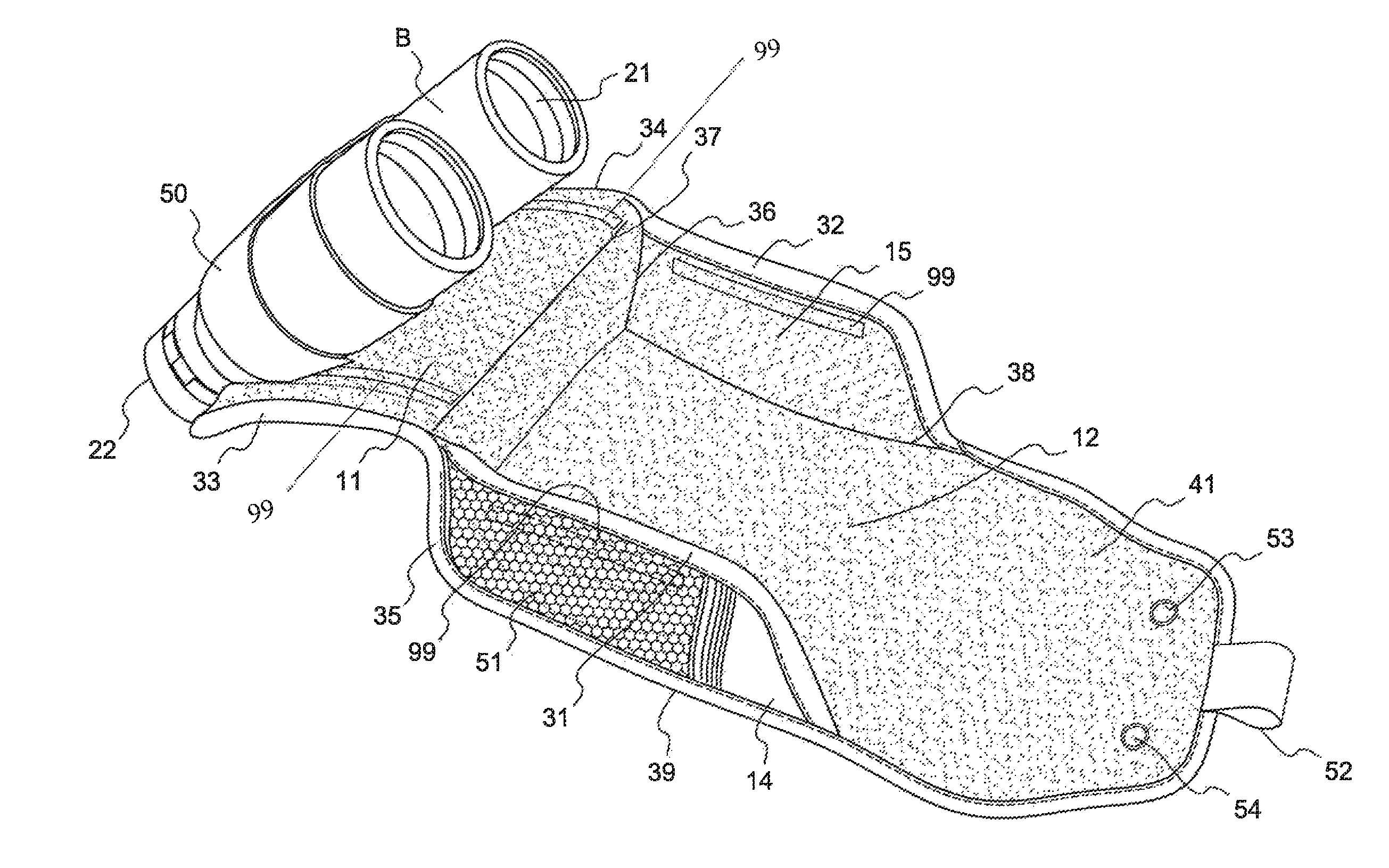
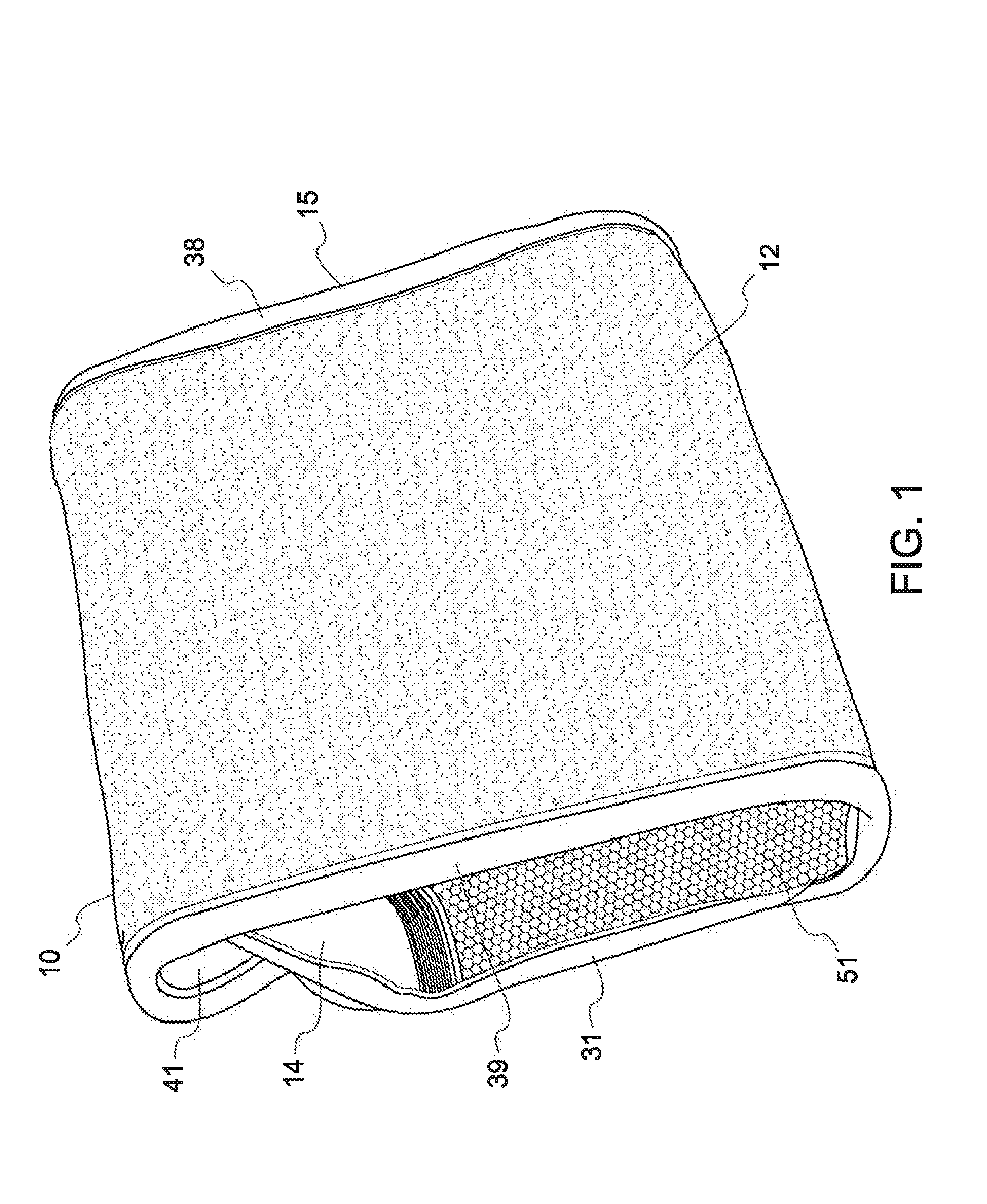
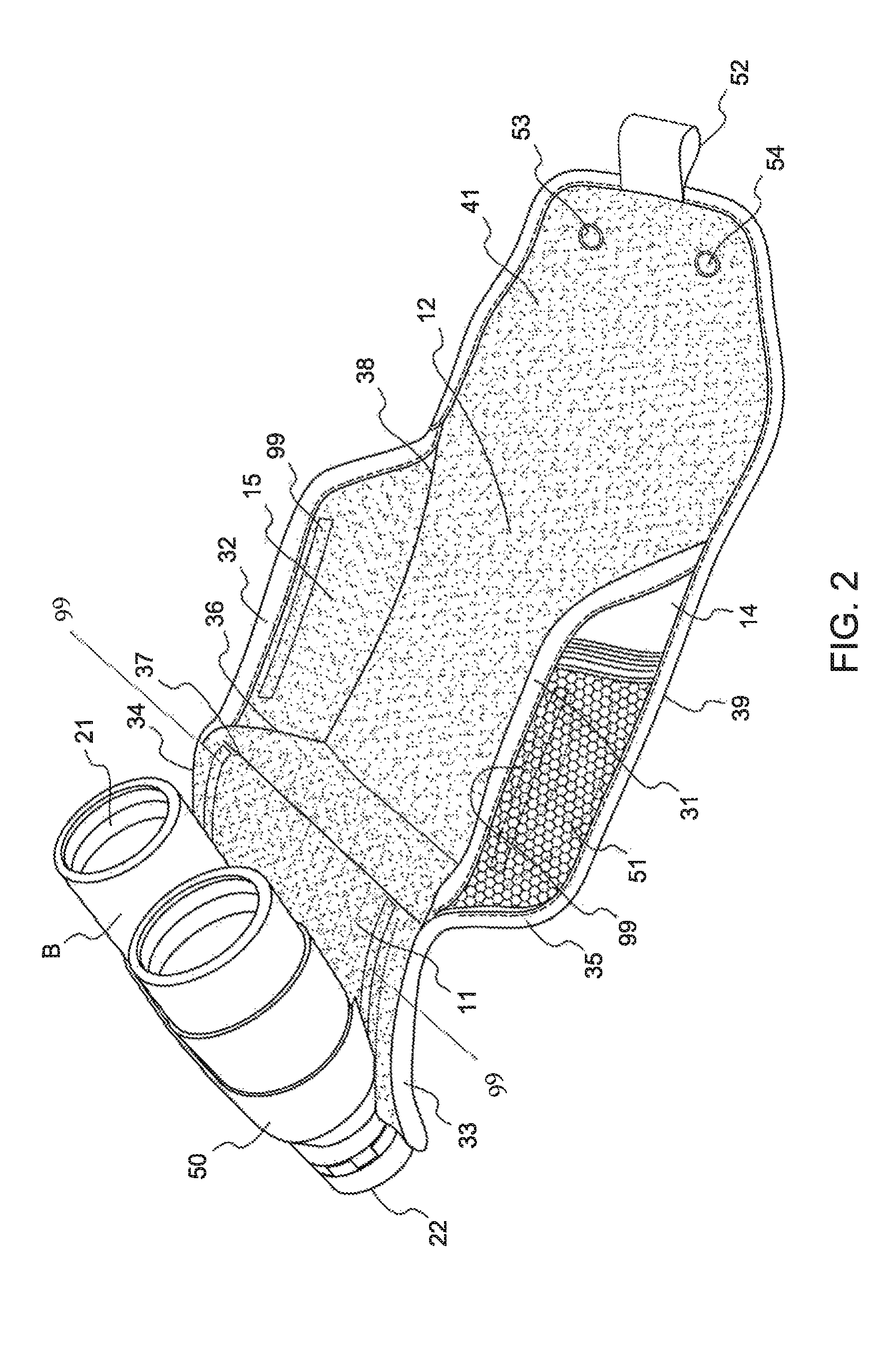
[0027]For example, in accordance with a first embodiment of the present invention, the protective carrying case 10 is designed for an optical instrument B and preferably a binocular having a “look into” end 22 and a “see out of” end 21. In this preferred embodiment, protective carrying case 10 composes a main panel 11, to which the optical instrument B is coupleable, a back panel 12 connected to the main panel 11 at one end 37, side panels 14, 15 are directly connected at corresponding edges 35, 36, 38, 39 to the back panel 12 and have edges 31, 32 which are releasably connected to corresponding edges 33, 34 of main panel 11. The back panel 12 is extended by a flap 41 which is re...


PUM


Abstract

A carrying case for a device having a “look into” end and a “see out of” end, wherein the carrying case comprises a main panel having an inner side surface to which a device is coupleable and also having at least a first edge; a back panel, having at least a first edge, and coupled to the main panel, such that the back panel is rotatable (i) away from the main panel to an open position and (ii) towards the main panel to a closed position; at least one side panel having at least a first edge alignable with the at least first edge of the main panel, and at least a second edge alignable with the at least first edge of the back panel, wherein at least one pair of alignable edges are releasably secured such that the edges are connected in the closed position and disconnected in the open position, and wherein in the open position a line of sight is created between an object, the “see out of” end of the device and the “look into” end of the device.

Description

BACKGROUND OF THE INVENTION[0001]The present invention relates generally to protective carrying cases thr devices with a “look into” end and a “see out of” end and more particularly relates to a novel and improved protective carrying case for optical instruments, more specifically binoculars, which protects the instrument while it is in storage and provides quick, quiet and easy access for the instrument to be used. Also provided herein are methods of using the cover of the present invention.[0002]Binoculars and other optical instruments are often used by hunters, bird watchers, and other sportsmen to view wildlife. To protect binoculars from damage sportsmen will often store the binoculars in a knapsack or other storage medium. If game or wildlife is sighted or if a need otherwise arises to have immediate access to the binoculars, however, such storage does not permit ready access. For example, once game is sighted the sportsman would wish to confirm the identification of game thro...

Claims


Application Information

Patent Timeline
IPC IPC(8): B65D85/38
CPCA45C11/08A45F5/00A45F2005/006
Inventor STUBEL, MARC A
Owner CARSON OPTICAL
Learn More