Pretensioner

a technology of pretensioner and piston, which is applied in the direction of pedestrian/occupant safety arrangement, safety belt, vehicular safety arrangement, etc., can solve the problem of loss of pressure for sliding the piston

Active Publication Date: 2012-03-13
KK TOKAI RIKA DENKI SEISAKUSHO
View PDF17 Cites 8 Cited by
  • Summary
  • Abstract
  • Description
  • Claims
  • Application Information

AI Technical Summary

Benefits of technology

[0009]Accordingly, the present invention has been made in consideration of the above-described problems, and the invention provides a pretensioner that can prevent or suppress a size-increase of a guarding section that is for preventing or suppressing gas generated by a gas generating section from being directly blown to a connection member such as a wire.
[0014]In this case, inside the gas passing portion, the gas guiding section is provided between the guard section and the gas generating section mounting portion provided in the pretensioner body, and the gas that is generated by the gas generating section is directed toward the base end side of the guard section when the gas passing the gas passing portion. For this reason, the gas that is jetted from the gas generating section is mainly blown to the vicinity of the base end of the guard section. As described above, since the guard section extends from the edge at the one end of the through hole, mechanical strength of the base end is higher than that of the tip end side. For this reason, even though the entire mechanical strength of the guard section against the pressure and the like of the gas that is generated by the gas generating section is not set to be high, the mechanical strength against the pressure of the gas can be secured.
[0021]The pretensioner according to the aspects of the invention can prevent or suppress a size increase of the guarding section for preventing or suppressing the gas generated by the gas generating section from being directly blown to the connecting member such as the wire.

Problems solved by technology

A leakage of the high-pressure gas from the through hole causes a loss of the pressure for sliding the piston.

Method used


Image

  • Pretensioner
  • Pretensioner
  • Pretensioner

Examples


Embodiment Construction

[0026]

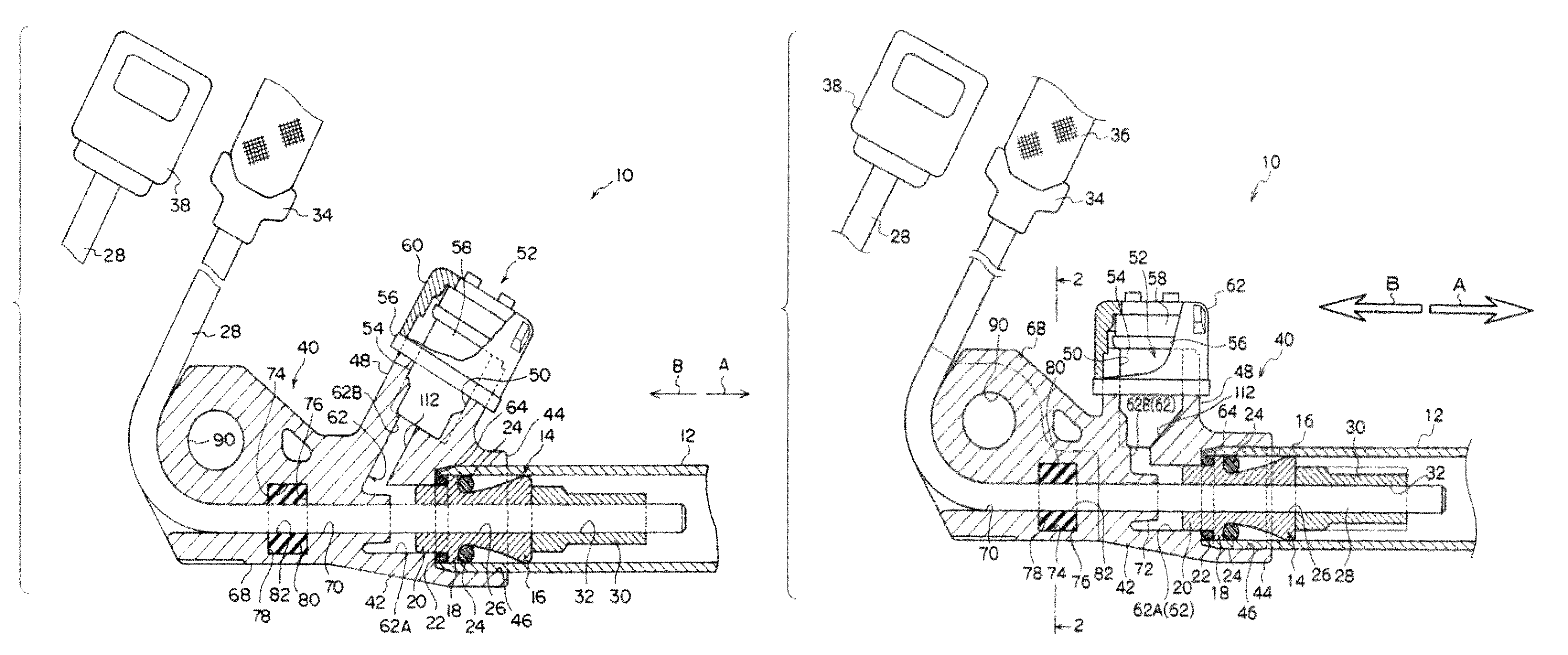
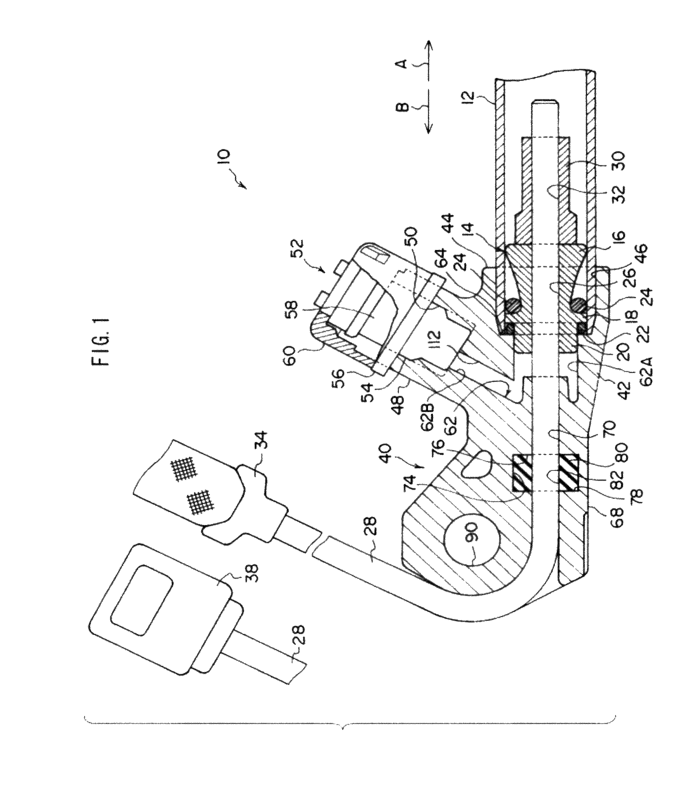
[0027]FIG. 1 is a cross-sectional view illustrating the configuration of a pretensioner 10 according to an exemplary embodiment of the invention.

[0028]As shown in FIG. 1, the pretensioner 10 includes a cylinder 12. The cylinder 12 is formed in a cylindrical shape (a tube shape) in which at least one of end portions thereof is opened. The cylinder 12 accommodates inside thereof a piston 14 that is formed by performing forge forming (molding) of metal. The piston 14 includes a piston body 16. The piston body 16 is configured such that an outer diameter gradually increases toward the side of a tip end (another end) of the cylinder 12 (side of a direction shown by an arrow A in FIG. 1), and, at least, it is formed into cone shape such that the outer circumferential shape of an end of the piston main body 16 at the tip end side of the cylinder 12 is almost equal to the inner circumferential shape of the cylinder 12, by cutting the forged molded work piece.

[0029]In an end of the pis...


PUM


Abstract

In the pretensioner, a guiding wall is provided in a generator-side passing portion of a gas passing portion, and an inner portion of the generator-side passing portion at a portion where the guard wall is set is located to a base end rather than a tip end of a wire protective cylinder. Further, a gas generator mounting hole and the generator-side passing portion is inclined to be directed the base end of the wire protective cylinder. For this reason, gas that is jetted from a gas generator is blown to the base end of the wire protective cylinder or a surrounding portion thereof. As a result, even though the thickness of the wire protective cylinder is not set to be large, it can be against pressure of the blown gas.

Description

CROSS-REFERENCE TO RELATED APPLICATION[0001]This application claims priority under 35 USC 119 from Japanese Patent Application No. 2008-266481 filed on Oct. 15, 2008, the disclosure of which is incorporated by reference herein.BACKGROUND OF THE INVENTION[0002]1. Field of the Invention[0003]The present invention relates to a pretensioner capable of increasing a tensile force of a webbing belt by pulling an anchor to which an end of the webbing belt is fastened or a buckle device in which a tongue provided at the webbing belt is attached constituting a seat belt device of a vehicle when rapid deceleration of the vehicle.[0004]2. Related Art[0005]A pretensioner (pre-loader) that is disclosed in Japanese Patent Application Laid-Open (JP-A) Nos. 2007-62600 and 2007-76493 includes a housing at which a cylinder and a gas generator are mounted. In the housing, a through hole that is through the inside and the outside is formed, and a wire where a base end thereof in a longitudinal direction...

Claims


Application Information

Patent Timeline
Patent Type & Authority Patents(United States)
IPC IPC(8): B60R22/46
CPCB60R22/1952B60R22/1955
Inventor SUGIYAMA, MOTOKIUKITA, MASARUMUROMACHI, TETSUSHI
Owner KK TOKAI RIKA DENKI SEISAKUSHO
Why Eureka
Try Eureka