Workpiece gripping device

a technology for gripping devices and workpieces, which is applied in the direction of tableware, hoisting equipment, and well accessories, etc. it can solve the problems of difficult to pick workpieces, no space can be secured around workpieces, and thin plate components that are adapted to be inserted between, so as to reduce the operation amount of each gripping pawl and minimize the space in which the gripping pawl may interfere during the gripping operation

Active Publication Date: 2012-03-13
FANUC LTD
View PDF17 Cites 81 Cited by
  • Summary
  • Abstract
  • Description
  • Claims
  • Application Information

AI Technical Summary

Benefits of technology

[0011]Accordingly, it is an object of the present invention to provide a workpiece gripping device which causes less interference with an object surrounding a workpiece to be picked and is applicable to various types of workpieces and suitable for the job of picking the workpiece out of a limited space.
[0012]In order to achieve this object, according to the present invention, there is provided a workpiece gripping device which includes a catching mechanism having a catching part capable of holding a workpiece by suction force or magnetic force and a rod-like part having the catching part mounted at an end thereof, at least two gripping pawls sandwiching and gripping the workpiece held by the catching part, a drive unit for supplying a drive power, and a transmission mechanism transmitting the drive power of the drive unit to the gripping pawls, wherein the transmission mechanism moves the gripping pawls along an axis of the rod-like part between a gripping position where the gripping pawls are projected beyond an end of the rod-like part on which the catching part is mounted and a retreated position where the gripping pawls are retreated behind the catching part toward an end of the rod-like part on the side opposite to the catching part, and the gripping pawls are moved to the gripping position along the axis of the rod-like part while shortening the distance between the gripping pawls.
[0013]According to this configuration, by arranging the gripping pawls at the retreated position, a state can be achieved in which no component parts of the gripping device other than the rod-like part supporting the catching part exists around the catching part. Therefore, the catching part can be brought near to the workpiece to be picked and the workpiece can be held and taken out by the catching part, while preventing the gripping device from interfering with objects surrounding the workpiece to be picked. In this process, the catching part holds the workpiece by suction force or magnetic force and therefore rarely damages the workpiece.

Problems solved by technology

Especially for workpieces densely stored or located near the side surface of the storage box, no space can be secured around the workpieces and the workpieces are sometimes difficult to pick.
Further, in the gripping devices disclosed in Japanese Unexamined Patent Publication Nos. 2002-331488 and 11-20997, the thin plate member adapted to be inserted to between workpieces cannot be suitably inserted to between the workpiece closely contacting the wall and the wall of the storage box in which the workpieces are stacked.
Therefore, it is sometimes difficult to pick such workpieces.
Further, when inserting the member in between workpieces, the member inserted may cause measurable damage on the workpiece surface, depending on the type of the workpiece or the magnitude of the force exerted between the stacked workpieces.
Therefore, the application of these gripping devices is limited.
The gripping device disclosed in Japanese Unexamined Patent Publication No. 2004-25326 has a plurality of gripping mechanisms and therefore is liable to become large.
This also easily causes interference with an object surrounding the workpiece to be picked.
Therefore, this gripping device is not suitable for carrying out a job in a limited space in a storage box or the like.

Method used


Image

  • Workpiece gripping device
  • Workpiece gripping device
  • Workpiece gripping device

Examples


first embodiment

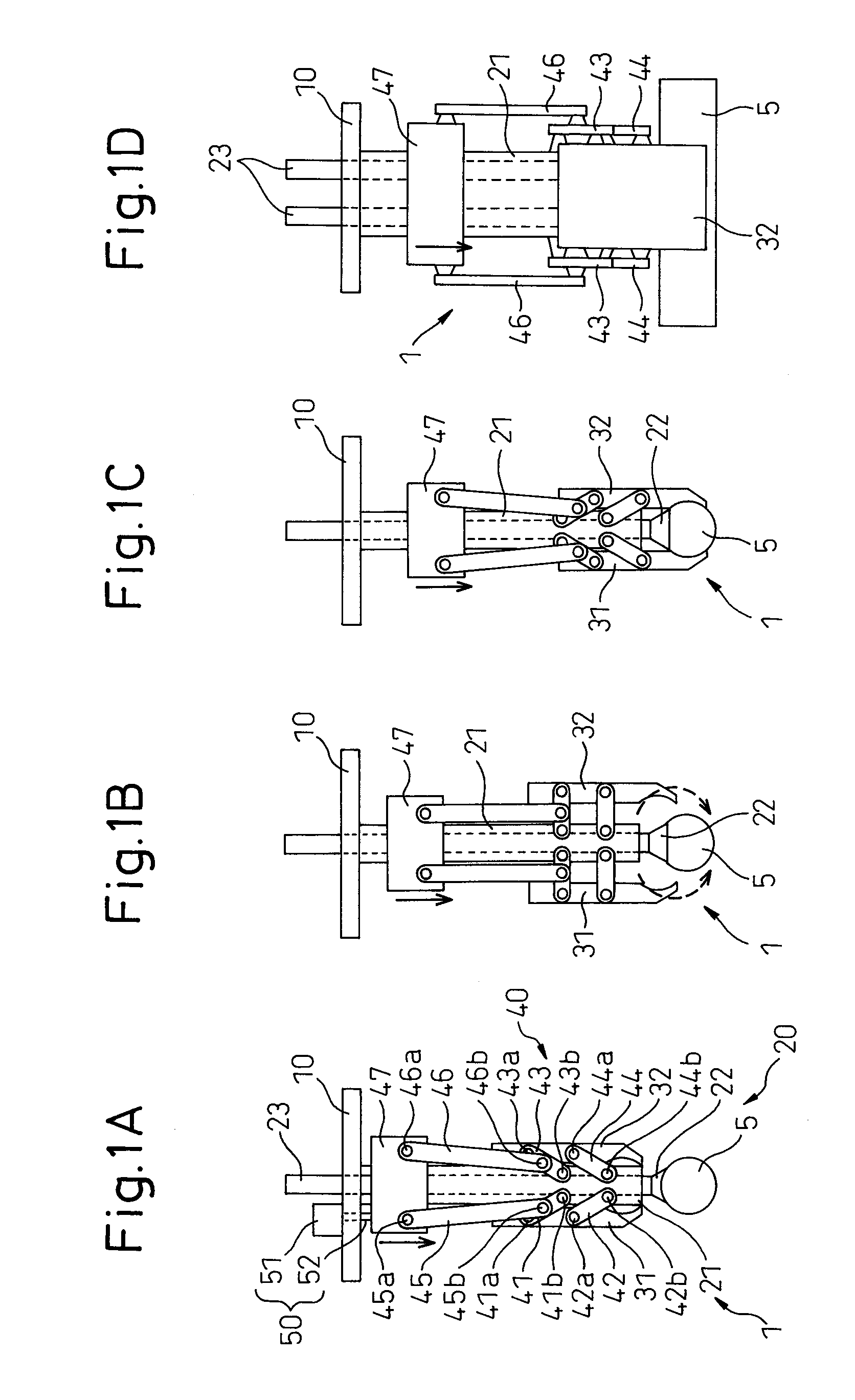
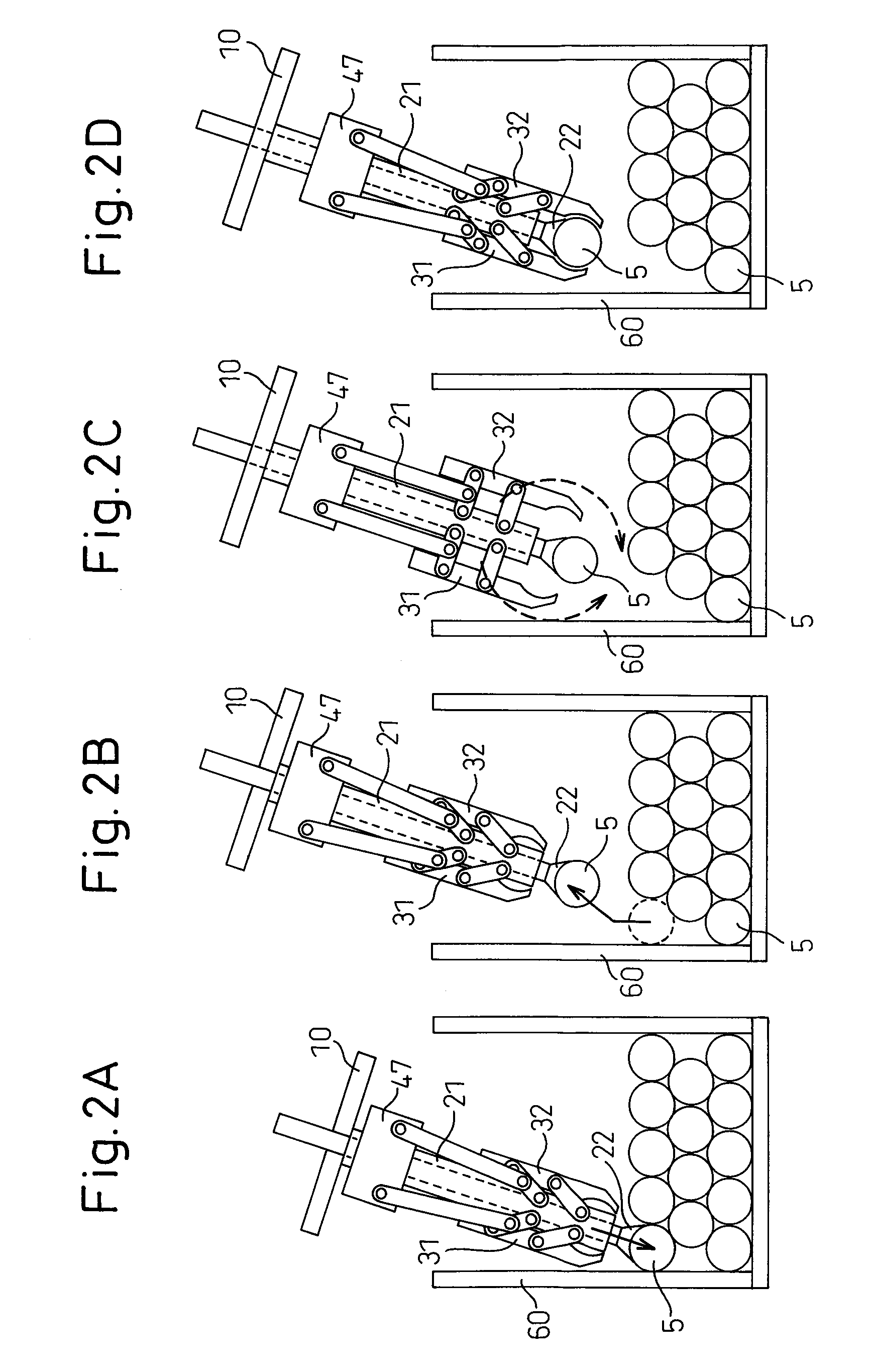
[0029]FIGS. 1A to 1D show a gripping device 1 according to a first embodiment of the present invention. As shown in the figure, this gripping device 1 is configured to catch a solid-cylindrical workpiece 5 by suction and further sandwich it from both lateral sides thereof to grip it. FIGS. 1A to 1C are front views as viewed in a direction parallel to an axis of workpiece 5 and show a gripping operation, in time series, after catching workpiece 5 by suction. FIG. 1D is a side view of gripping device 1 shown in FIG. 1C as viewed in a direction perpendicular to the axis of workpiece 5.

[0030]Gripping device 1 includes a base plate (gripping device base) 10 to be mounted at a forward end of an arm of a robot (not shown). The robot on which base plate 10 is mounted may have any of known configurations by which a position and a posture of base plate 10 or gripping device 1 can be changed as desired. The configuration of the robot is not directly related to the present invention and therefo...

second embodiment

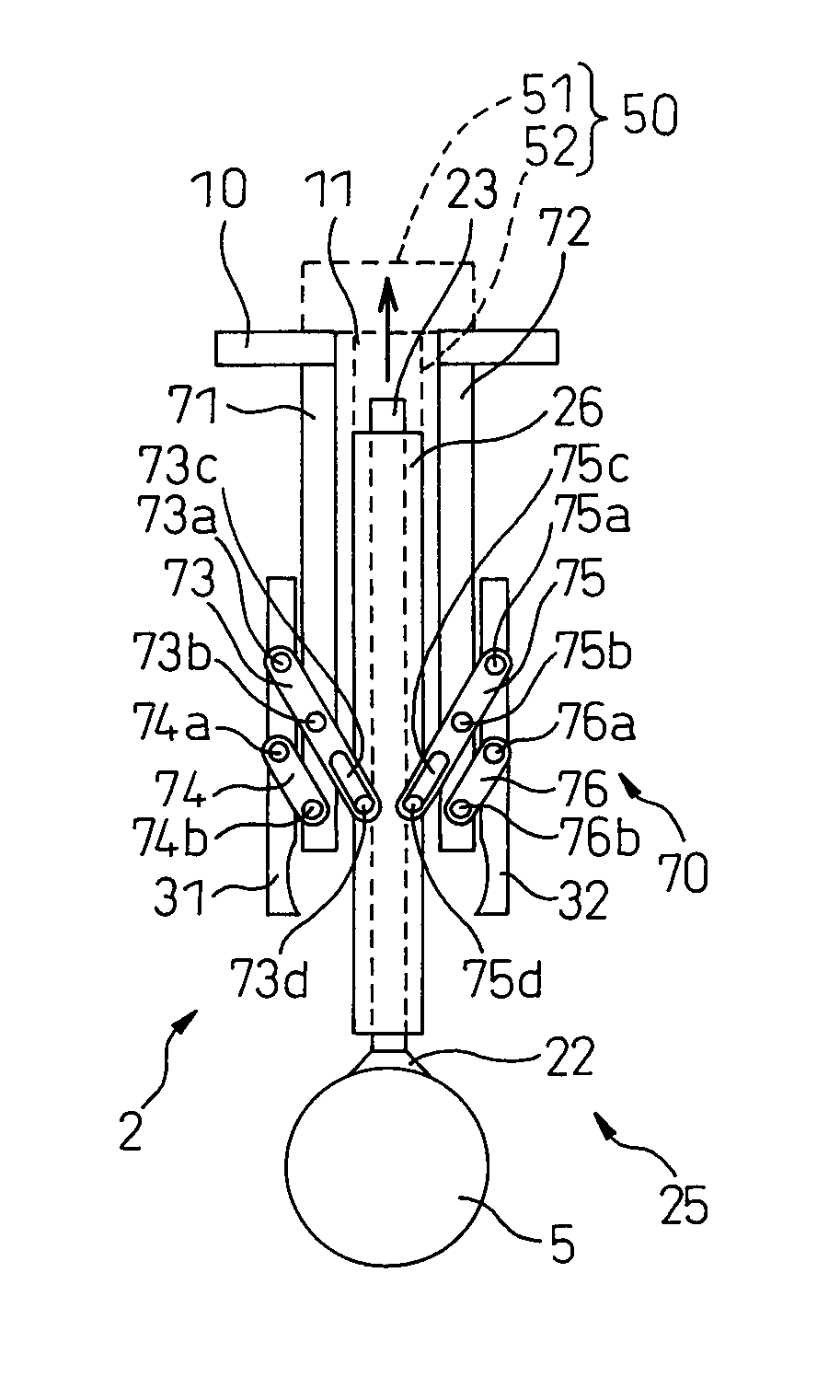
[0060]FIGS. 5A to 5D show a gripping device 2 according to a second embodiment of the present invention. In FIGS. 5A to 5D, parts corresponding to those of the first embodiment are denoted by the same reference numerals, respectively, and the detailed description thereof will be omitted.

[0061]According to this embodiment, in the primary catching mechanism 25, rod-like part 26 having suction pad 22 mounted at one end thereof is configured to be movable with respect to base plate 10. Base plate 10 is formed with an opening 11 which allows rod-like part 26 to pass therethrough. Base projection plates 71, 72 extending in a direction perpendicular to base plate 10 are coupled to the opposite edge portions of opening 11, respectively. Rod-like part 26 is configured to be movable through opening 11 between base projection plates 71, 72 along the axis thereof in a direction perpendicular to base plate 10.

[0062]Similarly to the first embodiment, any of various known devices such as an air cy...


PUM


Abstract

A workpiece gripping device includes a primary catching mechanism having a suction pad adapted to hold a workpiece by suction power and a rod-like part having the suction pad mounted on one end thereof, gripping pawls sandwiching and gripping the workpiece, a drive unit for supplying a drive power, and a transmission mechanism transmitting the drive power of the drive unit to the gripping pawls. The transmission mechanism moves the gripping pawls along an axis of the rod-like part between a gripping position where the gripping pawls are projected beyond the suction pad and a retreated position where the gripping pawls are retreated from the suction pad toward the base plate. The gripping pawls are moved to the gripping position along the axis of the rod-like part while shortening the distance between the gripping pawls.

Description

RELATED APPLICATIONS[0001]The present application is based on, and claims priority from, Japanese Application No. 2008-254508, filed Sep. 30, 2008, the disclosure of which is hereby incorporated by reference herein in its entirety.BACKGROUND OF THE INVENTION[0002]1. Field of the Invention[0003]The present invention relates to a workpiece gripping device for gripping a workpiece, and in particular, to a workpiece gripping device used for a robot to pick up individual workpieces from densely stacked workpieces or workpieces stacked in a box.[0004]2. Description of the Related Art[0005]In a manufacturing process, many workpieces can be stacked at a predetermined place or in a storage box, and it is known to use a robot to automate the picking of individual workpieces and supplying the workpieces to a subsequent process. In a picking job, it is necessary to avoid interference between the robot (specifically, a workpiece gripping device thereof) and an object (for example, other workpiec...

Claims


Application Information

Patent Timeline
Patent Type & Authority Patents(United States)
IPC IPC(8): B25B7/00
CPCB25J15/0266B25J15/0616
Inventor BAN, KAZUNORIWARASHINA, FUMIKAZUTAKIZAWA, SHOUTA
Owner FANUC LTD
Why Eureka
Try Eureka