[0019]For purposes of summarizing, certain aspects, advantages, and novel features of the invention have been described herein. It is to be understood that not all such advantages may be achieved in accordance with any one particular embodiment of the invention. Thus, the invention may be embodied or carried out in a manner that achieves or optimizes one advantage or group of advantages without achieving all advantages as may be taught or suggested herein.
[0020]In one embodiment, a method for controlling delay in a wireless communication system is provided. The method comprises a mobile station receiving a signal from a plurality of base stations; the mobile station measuring at least one signal delay for each of the plurality of base stations; and reporting the measured signal delay for each base station to a controller controlling the plurality of base stations.
[0021]The mobile station may receive an adjusted signal from each of the plurality of base stations as a result of reporting the measured signal delay. Desirably, each adjusted signal is received synchronously. In certain embodiments, the adjusted signal comprises an adjusted cyclic prefix length. A portion of the adjusted signal may comprise a truncated symbol duration or an idle time in between consecutive symbols.
[0022]A base station or controller may be configured to control delay in a wireless communication system by transmitting at least one signal to a plurality of mobile stations, wherein the signal is transmitted from two base stations, respectively, with an adjusted timing offset and / or adjusted cyclic prefix. The controller may receive a report from each of the plurality of mobile stations that includes data related to measured signal delay of the two base stations transmitting a signal to a respective mobile station.
[0023]Desirably, the controller may determine a time zone for each mobile station based on the received reports. The controller may also determine a cyclic prefix length and a timing offset between the two base stations based on the received reports. Depending on implementation a report may include one or more parameters such as a delay spread of a first base station; a delay spread of a second base station; a difference between an endpoint of the first base station's delay spread and a start point of the second base station's delay spread, and other timing information.
[0024]Based on the above parameters or timing information, the controller may select a set of mobile stations that can be served simultaneously by the two base stations according to, for example, the time zone of each mobile station, the determined cyclic prefix length, and the timing offset between the two base stations. In one embodiment, the controller may adjust the cyclic prefix length of a signal transmitted to the set of mobile stations in order to simultaneously serve the set of mobile stations by way of the two base stations.
[0025]In some embodiments, one or more mobile stations may receive a signal from a base station, and measure at least one signal delay for the base station. Each mobile station may report the signal delay to the base station and in response receive an adjusted signal from the base station. The signal may be adjusted with a conservative cyclic prefix chosen by the base station according to the measured signal delay from the mobile stations waiting for data to be received in the adjusted signal.
[0026]In accordance with another embodiment, a system comprising one or more logic units is provided. The one or more logic units are configured to perform the functions and operations associated with the above-disclosed methods. In accordance with yet another embodiment, a computer program product comprising a computer useable medium having a computer readable program is provided. The computer readable program when executed on a computer causes the computer to perform the functions and operations associated with the above-disclosed methods.
[0027]One or more of the above-disclosed embodiments in addition to certain alternatives are provided in further detail below with reference to the attached figures. The invention is not, however, limited to any particular embodiment disclosed.
[0028]The accompanying drawings, which are included to provide a further understanding of the invention and are incorporated in and constitute a part of this specification, illustrate embodiments of the invention and together with the description serve to explain the principles of the invention. Features, elements, and aspects of the invention that are referenced by the same numerals in different figures represent the same, equivalent, or similar features, elements, or aspects in accordance with one or more embodiments.
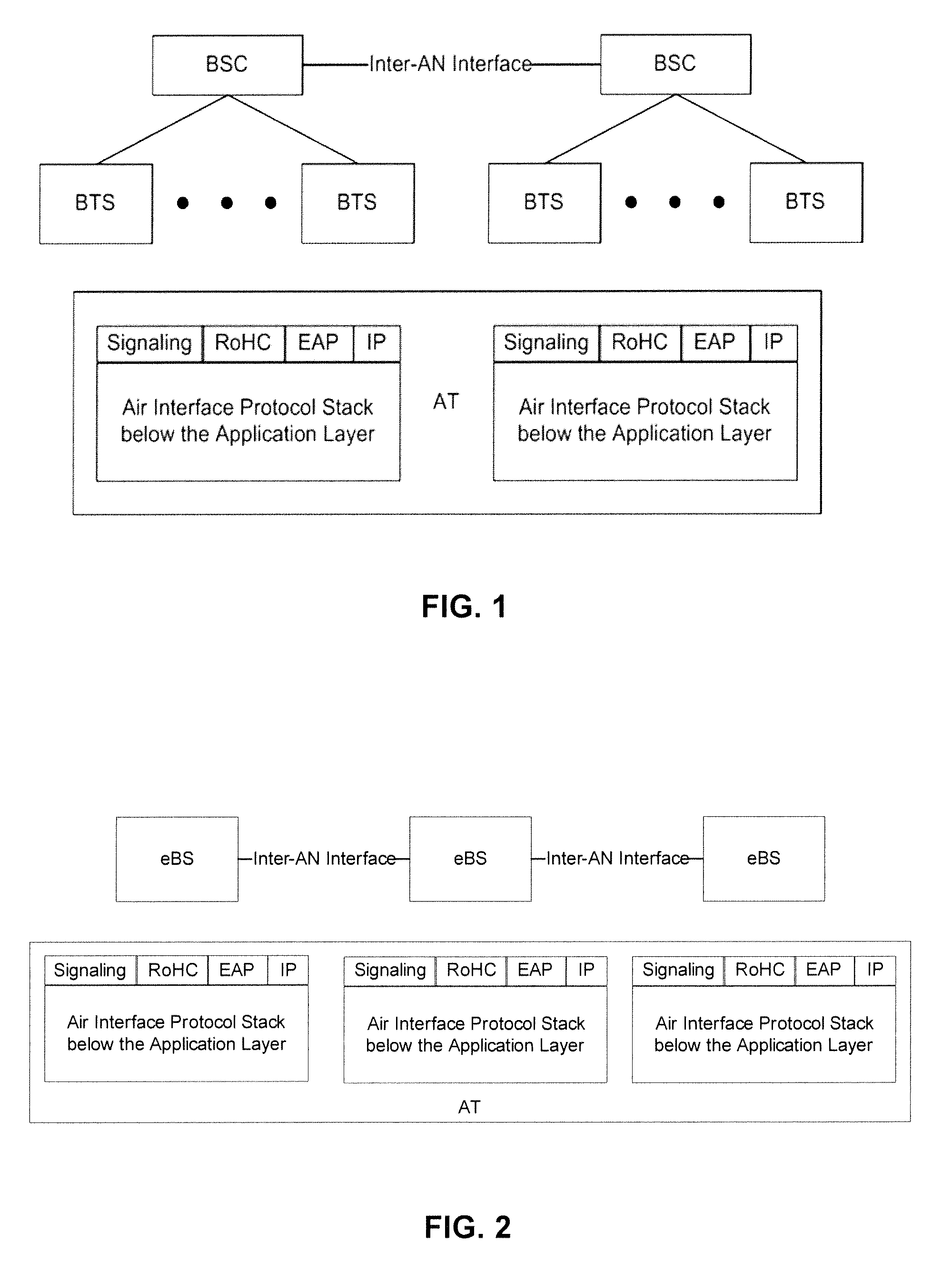
[0029]FIG. 1 illustrates a UMB centralized access network.
[0030]FIG. 2 illustrates a UMB distributed access network.
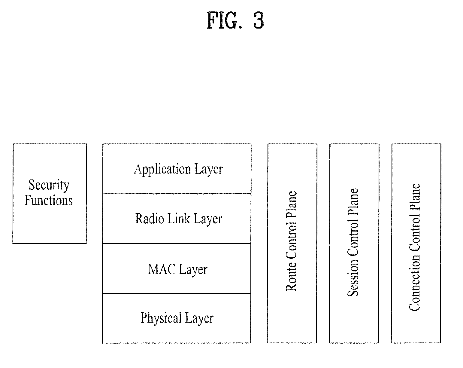
[0031]FIG. 3 illustrates UMB layers in which the application layer provides a signaling application, IP, RoHC, EAP and inter-technology tunneling.
[0032]FIG. 4 illustrates an exemplary communication environment, in accordance with one embodiment, wherein a plurality of base stations are in communication with a mobile station over forward link (FL) channels.
[0033]FIG. 5 illustrates an exemplary communication environment, in accordance with one embodiment, wherein a plurality of base stations are in communication with a plurality of mobile stations over forward link (FL) channels.
[0034]FIG. 6 illustrates a delay spread observed by a mobile station from two base stations communicating with the mobile station in accordance with one embodiment of the present invention.
[0035]FIG. 7 illustrates a time zone of a mobile station with regard to two base stations communicating with the mobile station in accordance with one embodiment of the present invention.
[0036]FIGS. 8A-8C illustrate a method for determining whether mobile stations can coexist in the same OFDM symbol as a reference mobile station in accordance with one embodiment of the present invention.
[0037]FIG. 9 illustrates an exemplary communication environment, in accordance with one embodiment, wherein a plurality of base stations are in communication with a plurality of mobile stations over reverse link (RL) channels.
[0038]FIGS. 10 and 11 illustrate exemplary mobile communication environments, in accordance with one embodiment, in which a base station is in communication with one or more mobile stations over the FL channel, with different mobiles allocated a subset of tones.
[0039]FIG. 12 is a block diagram of mobile communication device, which may be configured as an AT in accordance with embodiments of the present invention.
[0096]The logic implementation shown in the figures described specific operations as occurring in a particular order. In alternative implementations, certain logic operations may be performed in a different order, modified or removed and still implement preferred embodiments of the present invention. Moreover, steps may be added to the above described logic and still conform to implementations of the invention.
[0040]Frequency division multiplexing (FDM) is utilized to transmit multiple signals simultaneously over a single transmission path, in a wireless system. Each signal travels within its own unique frequency range (carrier), which is modulated by the data (text, voice, video, etc.). In one embodiment, an orthogonal FDM's (OFDM) spread spectrum technique is used to distribute the data over a large number of carriers that are spaced apart at precise frequencies.
[0041]The spacing provides the orthogonality in this technique which prevents the demodulators from seeing frequencies other than their own. Utilization of OFDM for data communication in a wireless network results in high spectral efficiency, resiliency to RF interference, and lower multi-path distortion. OFDM is particularly useful in a terrestrial broadcasting scenario where there are multipath-channels. That is, when the transmitted signal arrives at the receiver using various paths of different length.
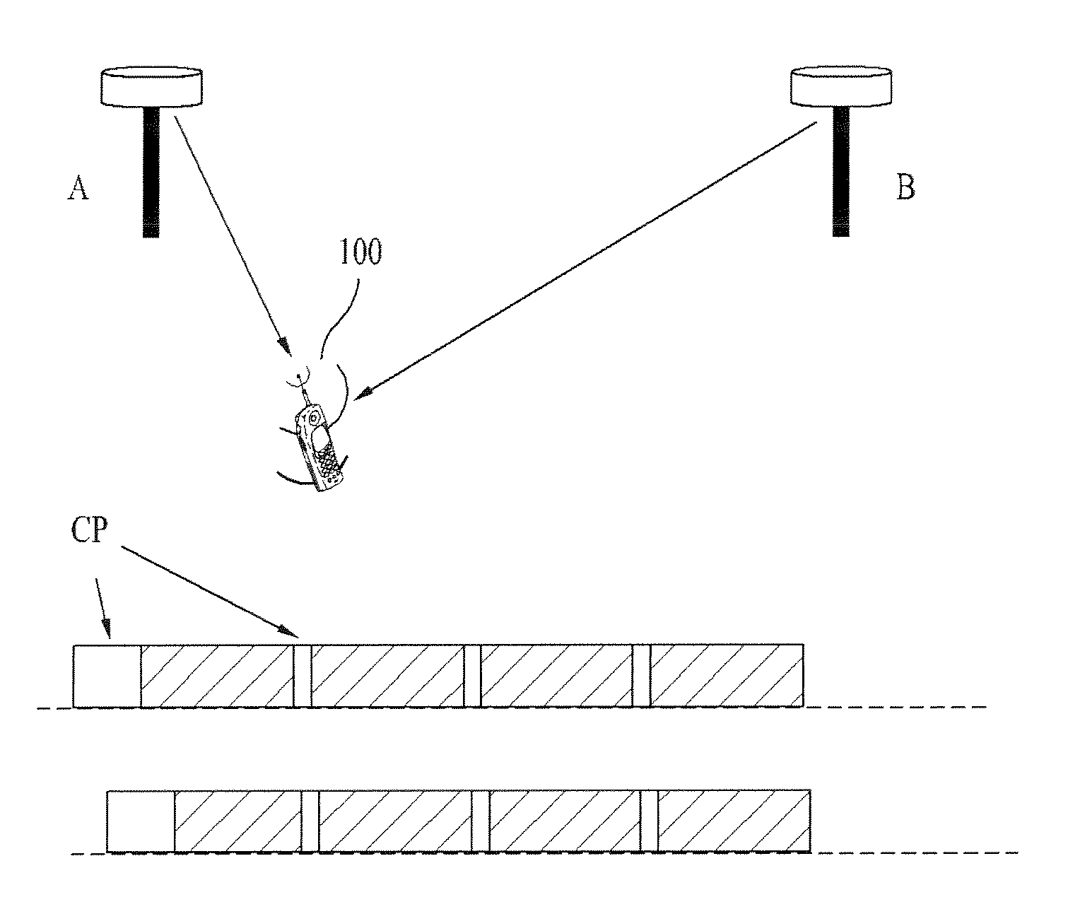
[0042]Multiple versions of the same signal may interfere with each other when received by the same receiver with a delay spread / offset greater than a cyclic prefix (CP) duration resulting in inter-symbol interference (ISI) and inter-carrier interference (ICI), making it difficult to extract the information originally transmitted. To resolve this problem, in one or more embodiments, delay controls and feedbacks related to systems with OFDM modulation are utilized as provided in further detail below.
[0043]In one embodiment, multiple data sources (e.g., base stations) may communicate with a mobile station over the forward link (FL) channel. Each base station or sector serves a mobile station and adjusts the transmission timing (e.g. adjusts the symbol duration of a first symbol in a packet) and the lengths of cyclic prefix of subsequent symbols, such that the OFDM symbols sent from the base stations arrive at a target mobile station synchronously. In the reverse link (RL), the RL sector or base station issues the timing adjustment commands to one or more mobile stations, such that the OFDM symbols arrive at the serving base station synchronously.
[0044]Accordingly, when signals carrying the same content from different sources arrive at a receiver, the sum of different delayed signals may have a different power profile. By controlling the delays and phases of the signals, the output signal power can be maximized. In addition, transmitters adaptively adjust symbol duration and FFT size based on the receiver's speed. The coherence time can be determined by observing the power control bits received. Depending on implementation, the receiver may be embedded in a mobile station, a base station, a relay station receiver. Further, a source may mean any of the following, without limitation: a transmitting antenna in a multi-antenna system, a base station, a mobile station, a relay stations or any combination thereof.
[0045]Referring to FIG. 4, an exemplary communication environment, in accordance with one embodiment is illustrated, wherein a plurality of base stations (e.g., A and B) are in communication with a mobile station 100 over forward link channels. In one embodiment, the delay may be controlled by mobile station 100 measuring the signal delay for each of the base stations A and B, in response to receiving a signal from each of the base stations A and B. The mobile station 100 may then report the measured signal delay for each base station A or B to a controller (not shown) for the base stations A and B.
[0046]The mobile station 100 may receive an adjusted signal from each of the base stations A and B as a result of reporting the measured signal delay. Desirably, each adjusted signal is received synchronously. In certain embodiments, the adjusted signal comprises an adjusted cyclic prefix length. A portion of the adjusted signal may comprise a truncated symbol duration or an idle time in between consecutive symbols, depending on implementation.
[0047]In some embodiments, a controller or a base station may control the delay by transmitting a signal to mobile station 100, and in response receive a report related to a measured signal delay for each base station A or B transmitting a signal to the mobile station 100. The controller may then coordinate with each base station A or B to adjust the signal in view of the report received from the mobile station 100. The adjusted signal may be transmitted to the mobile station 100 such that the adjusted signal arrives at the mobile station 100 synchronously with the adjusted signal transmitted by each base station A or B.
[0048]Mobile station 100 may listen to N base stations or sectors at the same time. The same data may be transmitted from N base stations with STC, or different data may be transmitted from N base station on the same tones by spatial multiplexing. Alternatively, different data may be received from N base stations on different tones. In one embodiment, mobile station 100 measures the relative delays of the signals from each FL serving base station by observing the respective pilot signals, for example. The mobile station 100 reports the relative delay for each base station. When a packet is scheduled to be sent to the mobile station 100, the first symbols are sent with a conservative cyclic prefix.
[0049]In one embodiment, referring to FIG. 4, for a base station with non-minimum delay, the symbol duration is shortened based on the reported relative delay, such that the symbol transition times of the signals from different base stations, perceived by the mobile station 100 are approximately synchronized. In one embodiment, each base station sends the second and the following symbols in the packet with a less conservative cyclic prefix (CP) which takes into account multi-path delay spreads. The CP, in some embodiments, may be configured to be the same among all base stations.
[0050]Accordingly, due to the shortened CP from the second symbol and beyond, the overall symbol duration may be shortened. This may increase the FL data rate. In some embodiments, instead of changing the delay, phase control can be used. For example, when a repeater is used with base station 100, the base station 100 can delay its transmission by the fiber propagation delay, so the delay spread of signal received at the mobile station 100 is reduced. The base station transmitter may adjust the transmission instances or frequency to maximize the received SNR while minimizing CP length, as noted above.
[0051]In accordance with another embodiment, a mobile station may be served by a plurality of base stations in the forward link (FL). Referring to FIG. 5, for example, mobile station 1 (MS1) may desire base station B (B) to be time advanced, or base station A (A) to be delayed in order to align symbol boundaries of signals received from A and B. Similarly, mobile station 2 (MS2) may desire A to be time advanced, or B to be delayed in order to align symbol boundaries of the signals received from A and B. In accordance with the present invention, a base station controller (BSC) may determine that the MS1 and MS2 can coexist in the same OFDM symbol given a certain CP size. Moreover, the BSC can determine a timing offset that satisfies both MS1 and MS2.
[0052]Referring to FIGS. 6 and 7, a delay spread from A to mobile station 1 (MS1) is identified as Sa and a delay spread from B to MS1 is identified as Sb. Accordingly, a difference (db−da) between any two paths from each base station A and B, respectively, is in the interval [x, y], wherein x is an offset from A's last delay component to B's first delay component and y is an offset from A's first delay component to B's last delay component. Moreover, a timing offset d may be applied between base stations A and B.

