[0042]It should be noted that the drawings have not been drawn to scale and that the dimensions of certain features have been exaggerated for the sake of clarity.
DETAILED DESCRIPTION OF EMBODIMENTS
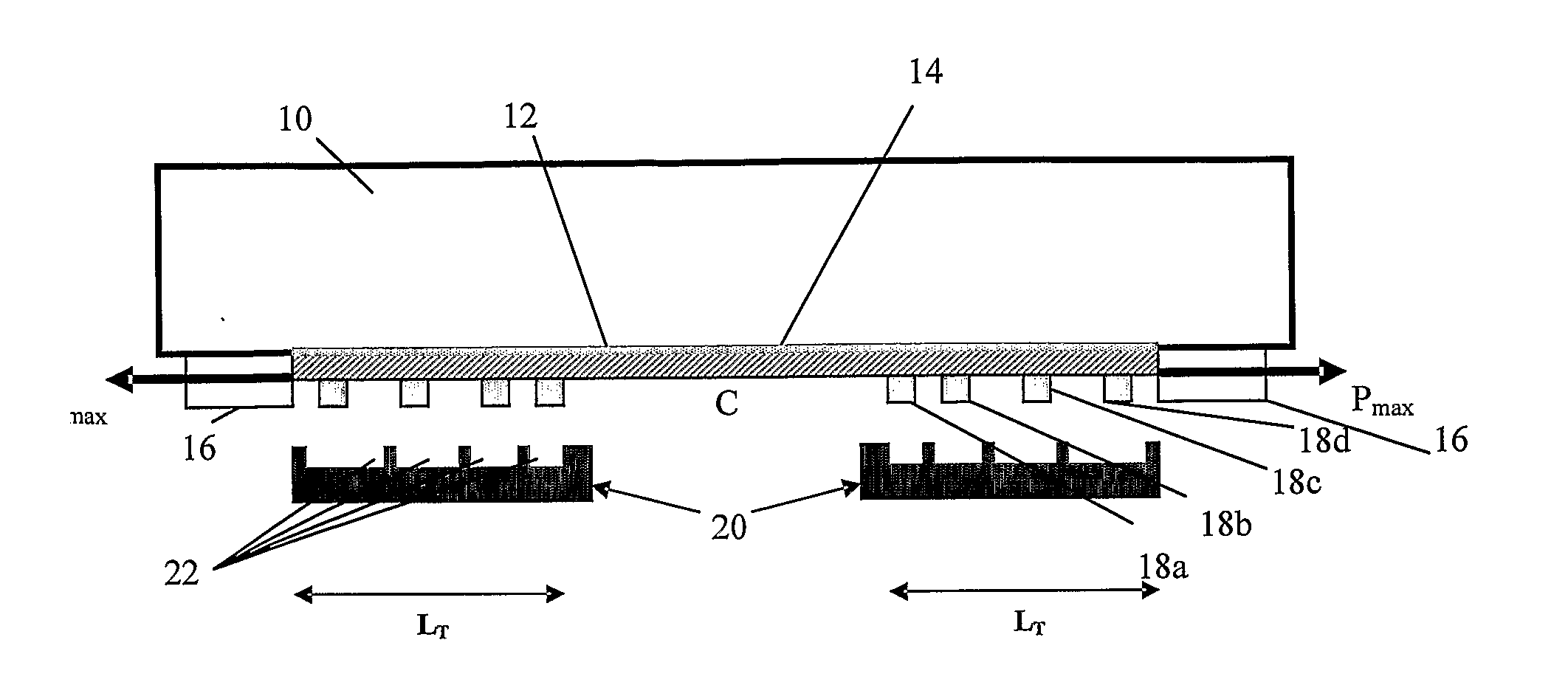
[0043]FIG. 1 shows a structural member 10, in the form of a beam constituting part of the span of a bridge for example. An FRP laminate 12 in the form of a lamellar strip, such as a pre-cured CFRP laminate, has been applied to the structural member by coating a surface of the structural member 10 with a continuous or discontinuous layer of curable adhesive 14 and pressing the FRP laminate 12 against the adhesive-coated surface. The FRP laminate 12 is applied to the bottom surface of the structural member 10 so that its fibres are parallel to the structural member's longitudinal axis.
[0044]A pre-stressing force, Pmax is then applied to each end of the FRP laminate 12 using a pre-stressing device 16 comprising two lockable units located in the vicinity of the ends of the FRP laminate 12 and attached to the structural member 10 for example. The exact degree of pre-stressing may be measured with strain gauges positioned on the FRP laminate 12, or by means of an integral force measuring device housed in the pre-stressing device 16. Two series of stop blocks 18 are glued to the FRP laminate 12 at a pre-determined distance from the ends of the FRP laminate 12.
[0045]The pre-stressing force, Pmax, is then decreased gradually in a continuous or step-like manner. While the pre-stressing force is being decreased, two moulds 20 that comprise a plurality of recesses 22 are fixedly arranged so as to prevent each stop block 18 from being displaced beyond a predetermined distance in the direction opposite to the direction of application of the pre-stressing force, Pmax. Each recess 22 in the mould 20 is namely arranged to receive one stop block 18. While the pre-stressing force is being decreased, the stop blocks 18 on the right-hand side of FIG. 1 are displaced to the left towards the centre C of the FRP laminate 12 and the stop blocks 18 on the left-hand side of FIG. 1 are displaced to the right towards the centre C of the FRP laminate 12 until the centre-most side wall 24 of each recess 22 prevents further movement of a corresponding stop block 18 towards the centre C of the FRP laminate 12. A treatment length, LT, at each end of the FRP laminate 12 will therefore be less pre-stressed than the FRP laminate 12 section at the centre C once the adhesive 14 has cured.
[0046]After curing of the adhesive 14, the pre-stressing device 16 is detached from the structural member 10 and the moulds 20 and the stop blocks 18 are preferably removed. Using this method a non-uniform axial force is created along the treatment length LT at each end of the FRP laminate 12, which decreases in the direction from the centre C of the FRP laminate to its ends, which causes a significant reduction in shear stress at the very ends of the FRP laminate 12.
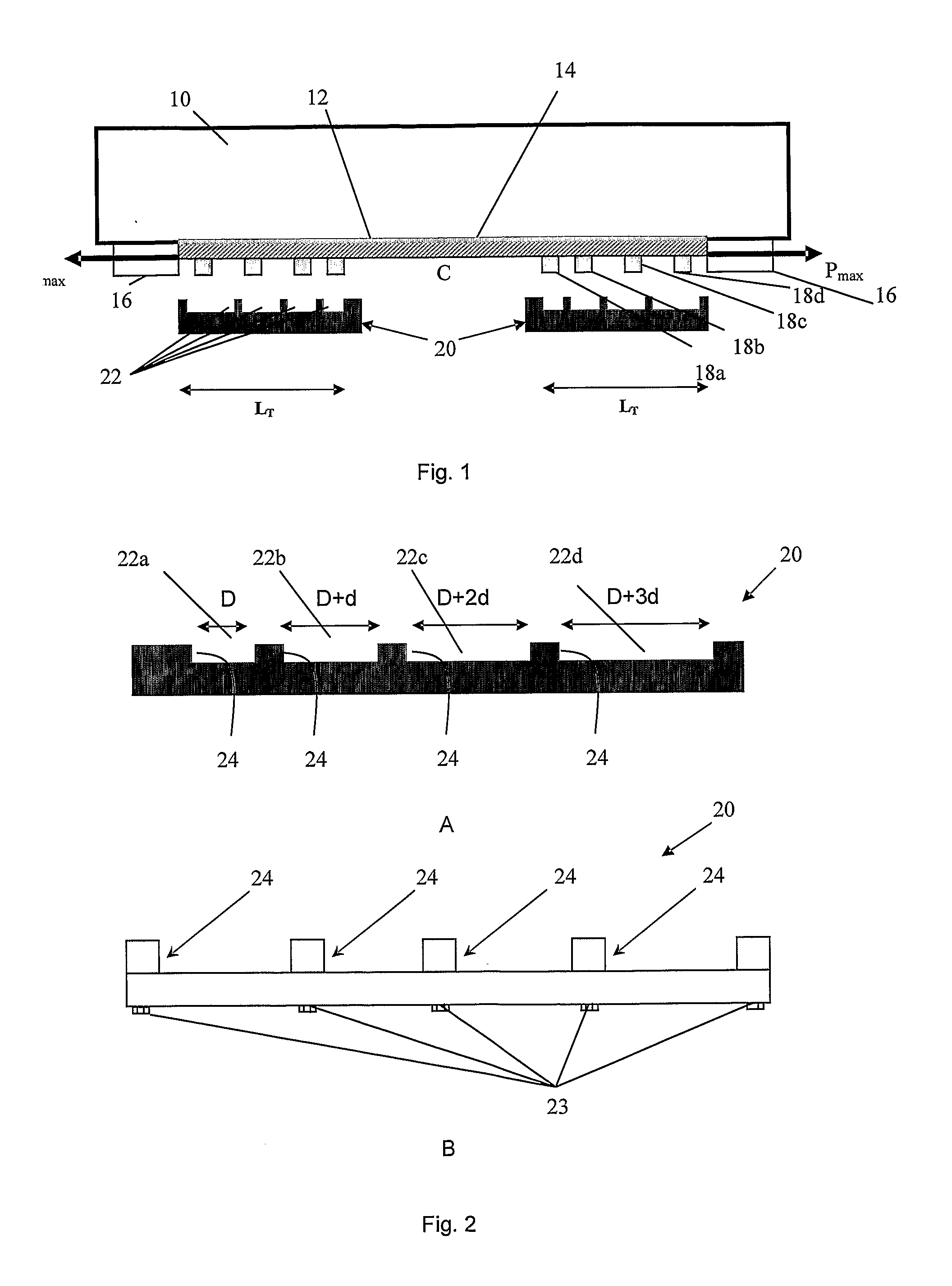
[0047]A mould 20 that is suitable for use in the method illustrated in FIG. 1 is shown in more detail in FIG. 2A. The illustrated mould 20 comprises four recesses 22a-22d of different widths, D to D+3d, whereby the mould 20, when in use, is arranged so that the width of each recess 22a-22d increases in the direction of application of the pre-stressing force. The mould 20 may be placed at the right-hand end of the FRP laminate 12 in FIG. 1, when four stop blocks 18a-18d each having a width D have been glued to the FRP laminate 12. The centre-most stop block 18a will be received in the centre-most recess 22a which also has a width and will thus be prevented from moving any further towards the centre C of the FRP laminate 12. The second stop block 18b will be prevented from moving any further towards the centre C of the FRP laminate 12 once the end of FRP laminate 12 has moved a distance d towards the centre of the FRP laminate 12 etc. The FRP laminate 12 will therefore be pre-stressed in a step-wise manner along the treatment length LT. It should be noted that the number, location and dimensions of the recesses 22a-22d along the mould 20 and the number, location and dimensions of stop blocks 18 along the FRP laminate 12 will of course depend on the pre-stressing profile that it is desired to obtain along the FRP laminate 12, which in turn depends on the particular application.
[0048]FIG. 2A shows a solid mould 20 that can be used for a specific type of laminate when applying a specific pre-stressing force. Alternatively a polylithic mould may be used in a method according to an embodiment of the invention. The mould 20 shown in FIG. 2B comprises movable blocks 18 that may be releasably, or non-releasably secured, by means of bolts 23 for example, at any position along the length of the mould 20. The space 22 between the blocks 18 may therefore be adjusted depending on the type of laminate and the pre-stressing force being used in a particular application.
[0049]FIG. 3 schematically shows an alternative method for applying an FRP laminate 12 to a structural member 10 which is similar to the method described in conjunction with FIGS. 1 and 2 but where the ends of the mould 20 (and not the ends of the FRP laminate 12) are clamped in a pre-stressing device 16 for example. The mould at the right-hand side of FIG. 3 is placed in the opposite direction to that shown in FIG. 2 whereas the mould at the left-hand side of FIG. 3 is placed as shown in FIG. 2. A pre-stressing force, Pmax, is applied to the mould 20, whereby the pre-stressed state of the mould 20 is consequently transferred to the FRP laminate 12. The pre-stressing force, Pmax, is then decreased gradually in a continuous or step-like manner. In this embodiment of the invention, the mould 20 therefore acts as both displacement-limiting means and as a means for indirectly applying a pre-stressing force to the FRP laminate 12.
[0050]According to an alternative embodiment of the invention an FRP laminate 12 may be subjected to a non-uniform pre-stressing and adhered to the structural member 10 in a non-uniformly pre-stressed state. A mould 20 may namely be used to apply an increased pre-stressing force to a length, LC, of the FRP laminate 12 so that the FRP laminate 12 along that length, LC, will be more pre-stressed than the FRP laminate 12 along a length section, LT, adjacent to that length LC, when the adhesive 14 has cured.
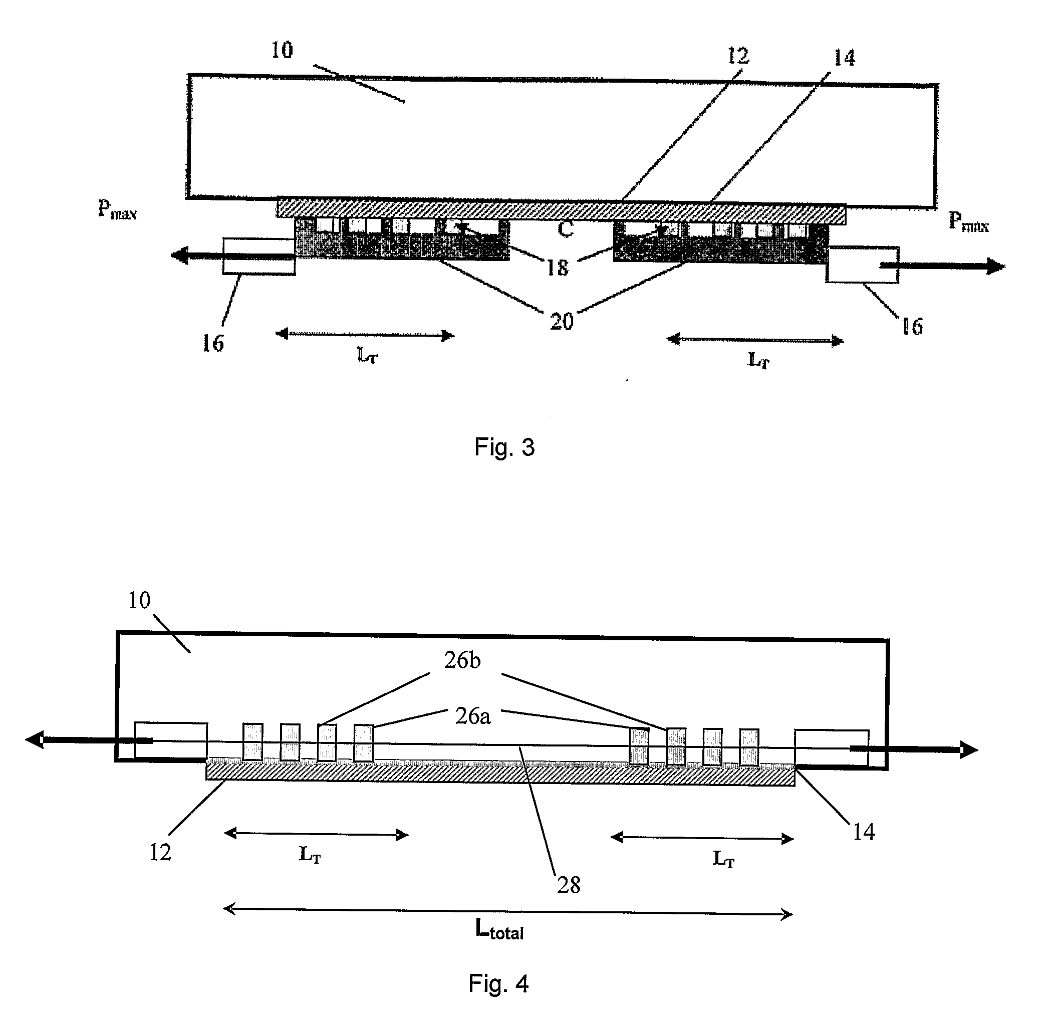
[0051]FIG. 4 shows a structural member 10 to which an FRP laminate 12 is being applied using a method according to a third embodiment of the invention. The method comprises the steps of subjecting a structural member 10 to non-uniform pre-stressing along a length, Ltotal, and adhering the FRP laminate 12 to the structural member in a non-stressed state. The non-uniform pre-stressing of the structural member 10 may be carried out by installing a plurality of pairs of mechanical posts 26 at predetermined positions near the surface of the structural member 10, whereby the two mechanical posts 26 of each pair are located one at each end of the structural member 10, and interconnecting the mechanical posts 26 with a pre-stressing rod 28 or some other pre-stressing means. Grooves may for example be cut in the structural member the mechanical posts 26 may be mechanically and/or adhesively fastened inside each groove.
[0052]The pre-stressing in this procedure is carried out in several steps. In the first step, the total pre-stressing force, Pmax, is applied to the structural member 10. Two nuts of the two inner mechanical posts 26a are tightened so that the pre-stressing rod 28 between the two inner mechanical posts 26a is maintained at the total pre-stressing force, Pmax. The pre-stressing force is then reduced by a predetermined amount, such as by 20%, and the two nuts of the adjacent mechanical posts 26b are tightened so that the pre-stressing rod 28 between those two mechanical posts 26b is maintained at that reduced pre-stressing force. This procedure is continued towards the ends of the structural member 10. Once the procedure is completed, curable adhesive 14 is applied to the bottom surface of the structural member 10 and then an FRP laminate 12 is applied to that surface in a non-stressed state. Once the adhesive has cured, the pre-stressing force is released by opening the nuts of each pair of mechanical posts 26 starting with the mechanical posts 26 located closest to the ends of the structural member 10 and working inwards towards the centre, C. The pre-stressing force is thus transferred from the structure member 10 to the FRP laminate 12. Even though the structural member 10 has to be modified somewhat to install the mechanical posts 26, an advantage of this method is that neither a pre-stressing device nor a mould is required.
[0053]FIG. 5 shows the axial force and shear stress versus the distance from the end (0) of an FRP laminate 12 towards its centre before treatment, i.e. when a pre-stressed FRP laminate is adhered to a non-pre-stressed structural member (see the continuous lines in FIG. 5), and after treatment, i.e. when a method according to an embodiment of the invention has been used to apply an FRP laminate to a structural member (see the dashed lines in FIG. 5). Using a method according to any of the embodiments of the invention reduces the slope of the axial force curve at the ends of the FRP laminate along the treatment length LT. FIG. 5 shows that the treatment length, LT, is divided into several steps. The magnitude of the axial force is constant in each step. The accumulation of shear stress is thereby prevented by these constant force intervals, i.e. the steps break up the high shear stress curve and distribute it along the treatment length, LT, of the FRP laminate.
[0054]It should be noted that an FRP laminate 12 need not necessarily be applied in a substantially horizontal orientation to the underside of a structure, such as a bridge, but may be applied in any position or orientation on an interior surface (such as the inside of a pipe) or an exterior surface of a structure where reinforcement is required. Furthermore, an FRP laminate 12 need not be of uniform thickness as shown in the figures, it need not be applied to a planar surface, and it may be of any shape, length and size.
[0055]Further modifications of the invention within the scope of the claims would be apparent to a skilled person. For example it would be obvious for a skilled person that a plurality of FRP laminates having their fibres aligned in different directions could be applied to a structural member using a method according to an embodiment of the invention in order to provide the desired strengthening.