

Device for assembling and disassembling a bicycle chain
a technology for bicycle chains and components, applied in the field of bicycle chain components, can solve the problems of inconvenient use of devices, and achieve the effect of convenient and simple assembly of bicycle chains
- Summary
- Abstract
- Description
- Claims
- Application Information
AI Technical Summary
Benefits of technology
Problems solved by technology
Method used
Image

Examples
Embodiment Construction
[0021]The present invention will be clearer from the following description when viewed together with the accompanying drawings, which show, for purpose of illustrations only, the preferred embodiment in accordance with the present invention.
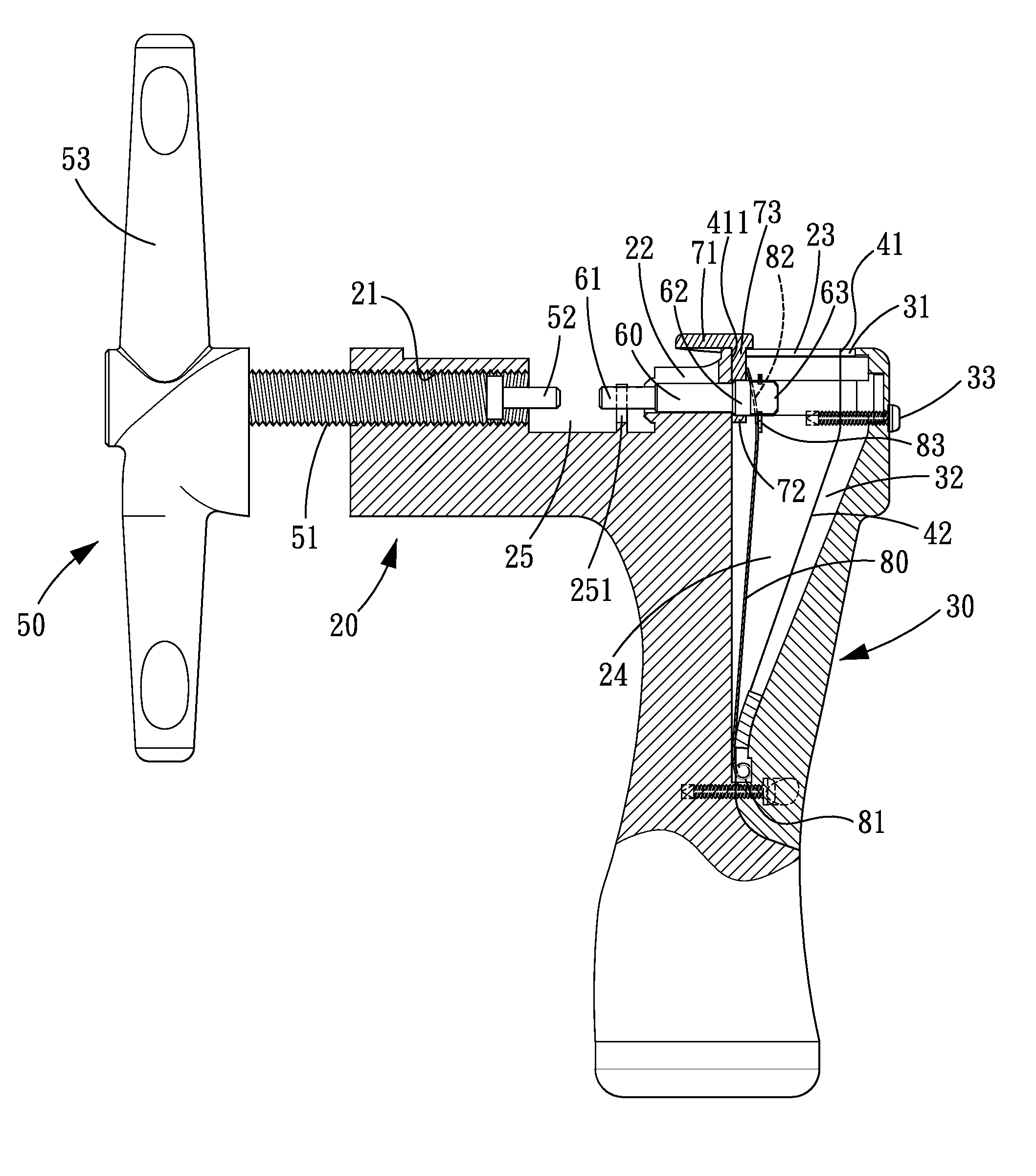
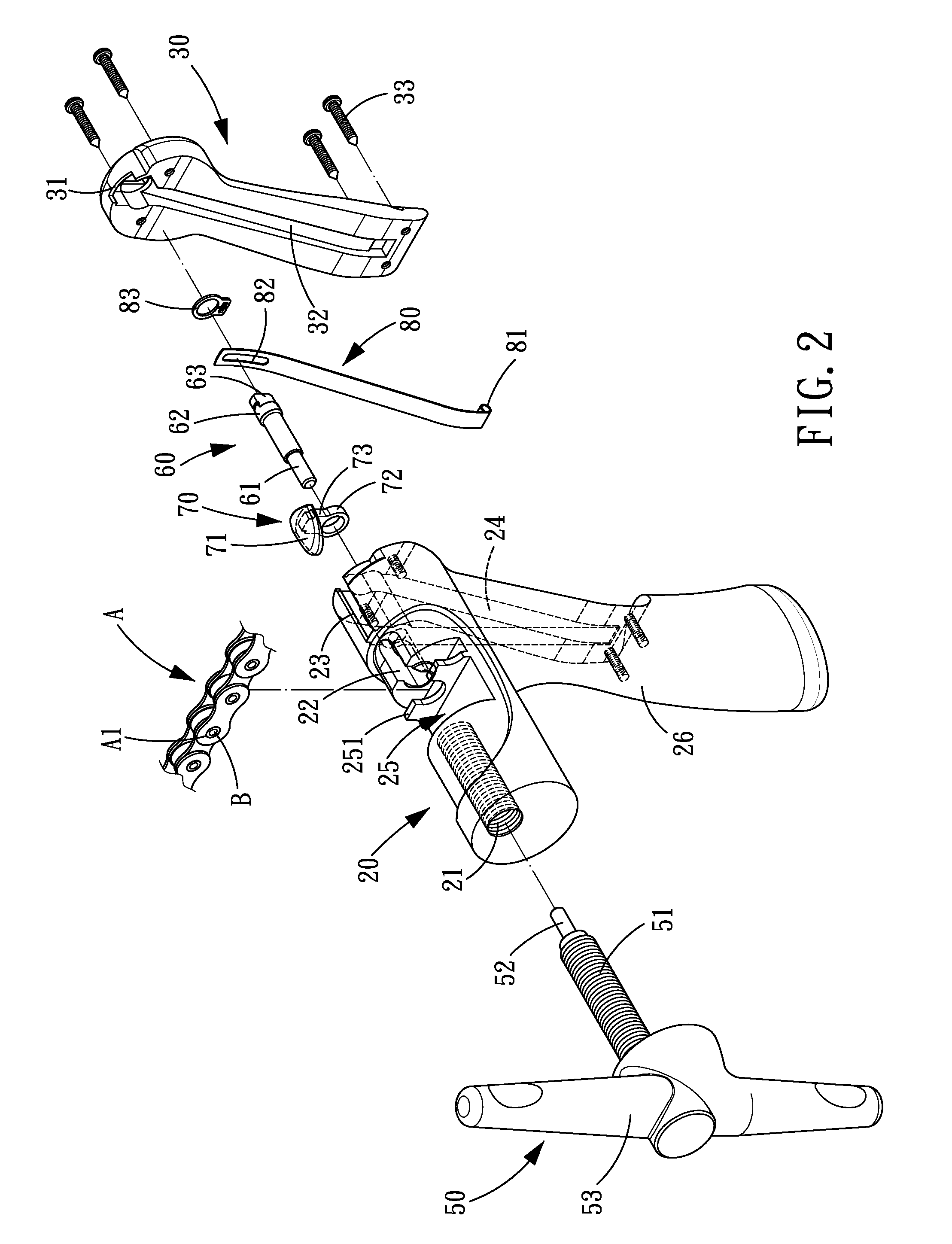
[0022]Referring to FIGS. 2-5, a device for assembling and disassembling a bicycle chain in accordance with the present invention comprises a main body, an actuating member 50, a rod member 60, a pulling member 70, and an elastic plate 80.
[0023]The main body includes an assembling seat 20 and a rear cap 30. The assembling seat 20 includes a threaded hole 21 and an assembling hole 22 that are coaxially arranged. The assembling seat 20 further includes a first sliding groove 23 in communication with the assembling hole 22, a first groove 24 in communication with the assembling hole 22 and the first sliding groove 23, and an assembling space 25 between the threaded hole 21 and the assembling hole 22. The assembling space 25 includes a positioning pro...
PUM
| Property | Measurement | Unit |
|---|---|---|
| elastic restoring force | aaaaa | aaaaa |
| elastic | aaaaa | aaaaa |
| pushing force | aaaaa | aaaaa |
Abstract
Description
Claims
Application Information