Contact device
a contact device and contact technology, applied in the direction of magnets, contact mechanisms, magnets, etc., can solve the problems of inability to ensure winding space, power consumption cannot be reduced, and the efficiency of magnetic efficiency is reduced, so as to facilitate assembly tasks and reduce vibration generated by the impact of movable iron cores , the effect of high productivity
- Summary
- Abstract
- Description
- Claims
- Application Information
AI Technical Summary
Benefits of technology
Problems solved by technology
Method used
Image
Examples
first embodiment
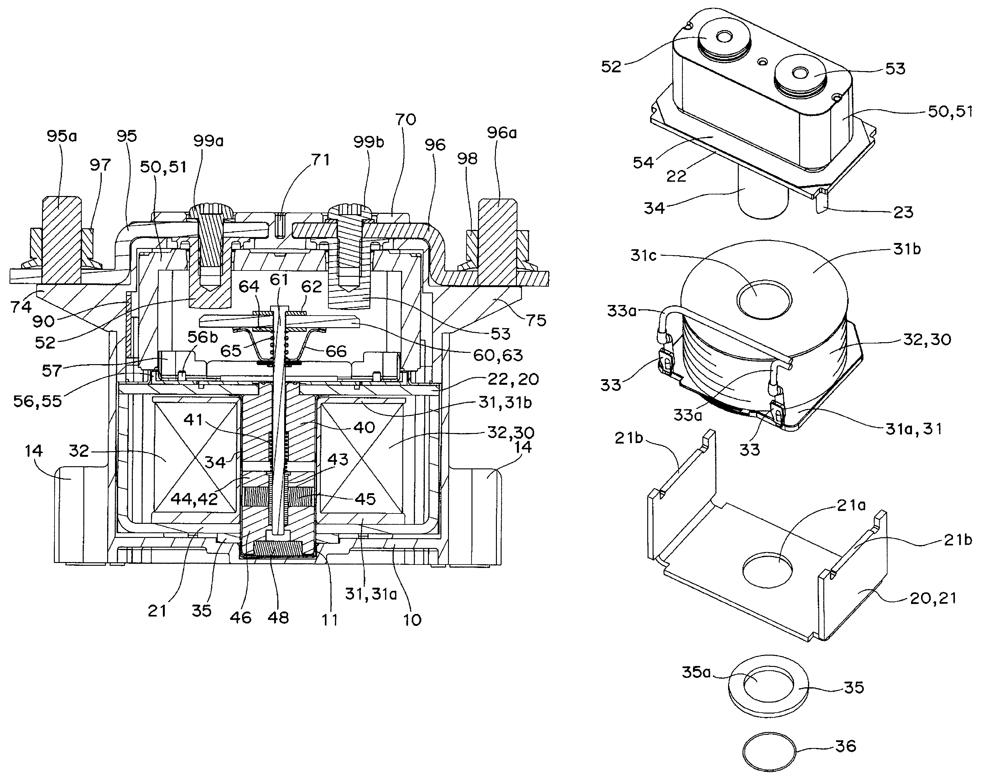
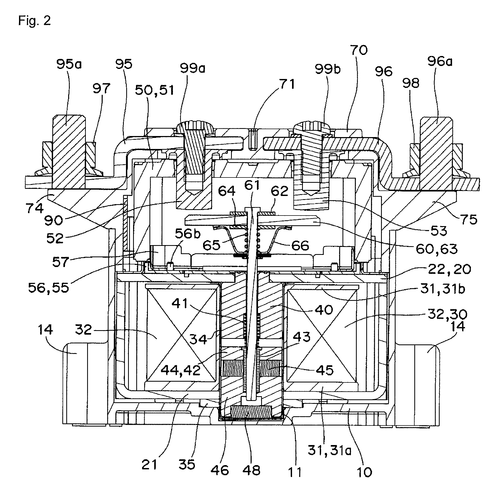
[0044]The first and second electromagnetic iron pieces 62, 64 of the movable contact block 60 have structures such that both ends of the first electromagnetic iron piece 62 contact the upper surface of both ends of the second electromagnetic iron piece 64, as shown in FIG. 11B. According to the present embodiment, when large current flows to the movable contact 63 at the initial stage in which the movable contact 63 is contacting the fixed contact terminals 52, 53, the first electromagnetic iron piece 62 and the second electromagnetic iron piece 64 attract each other, thereby pushing the movable contact 63 against the fixed contact terminals 52, 53. Thus, the movable contact 63 attracts to the fixed contact terminals 52, 53 without repelling against the fixed contact terminals 52, 53, whereby the arc does not create and contact welding does not occur.
[0045]The first and second electromagnetic iron pieces 62, 64 are not limited to the above embodiment, and may be configured as descr...
second embodiment
[0046]For example, as shown in FIG. 14A, both end faces of the first electromagnetic iron piece 62 may be adjacent to the opposing inner side surface of the second electromagnetic iron piece 64 having a substantially U-shaped cross section (second embodiment). According to the present embodiment, both end faces of the first electromagnetic iron piece 62 face the inner side surface of the second electromagnetic iron piece 64 at the initial stage in which the movable contact 63 is contacting the fixed contact terminals 52, 53. However, both end faces of the first electromagnetic iron piece 62 project out from both end faces of the second electromagnetic iron piece 64 at the stage the movable contact 63 contacts the fixed contact terminals 52, 53 with a predetermined pressure and the operation is completed. Thus, the magnetic resistance is small and large attractive force can be generated at the initial stage in which the movable contact 63 is contacting the fixed contact terminals 52,...
third embodiment
[0047]As shown in FIG. 14B, the first and second electromagnetic iron pieces 62, 64 having substantially L-shaped cross sections may be arranged to contact each other (third embodiment). According to the present embodiment, the parts can be commoditized since the first and second electromagnetic iron pieces 62, 64 have the same shape, which facilitates part management.
[0048]As shown in FIG. 14C, the first and second electromagnetic iron pieces 62, 64 having substantially U-shaped cross sections may be arranged such that perpendicular end faces thereof contact each other (fourth embodiment). According to the present embodiment, the parts can be commoditized similar to the second embodiment, which facilitates part management.
PUM
| Property | Measurement | Unit |
|---|---|---|
| magnetic efficiency | aaaaa | aaaaa |
| thickness | aaaaa | aaaaa |
| magnetic resistance | aaaaa | aaaaa |
Abstract
Description
Claims
Application Information
 - R&D
- Intellectual Property
- Life Sciences
- Materials
- Tech Scout
- Unparalleled Data Quality
- Higher Quality Content
- 60% Fewer Hallucinations
Browse by: Latest US Patents, China's latest patents, Technical Efficacy Thesaurus, Application Domain, Technology Topic, Popular Technical Reports.
© 2025 PatSnap. All rights reserved.Legal|Privacy policy|Modern Slavery Act Transparency Statement|Sitemap|About US| Contact US: help@patsnap.com


