Method and device to compensate for baseline wander

a baseline wander and compensation method technology, applied in pulse technique, dc level restoring means or bias distort correction, baseband system details, etc., can solve the problem that the application is unaware of any attempts, and achieve the effect of reducing baseline wander and superior baseline compensation

Active Publication Date: 2012-03-20
MARVELL ASIA PTE LTD
View PDF44 Cites 11 Cited by
  • Summary
  • Abstract
  • Description
  • Claims
  • Application Information

AI Technical Summary

Benefits of technology

[0014]The invention allows for superior baseline compensation using a unique compensation approach, which results in a significant reduction in baseline wander and other advantages apparent from the discussion herein.

Problems solved by technology

Applicant is not aware of any attempts to combine the individual compensation approaches discussed herein, which may be due, at least, in part to the complexity involved in combining these prior compensation approaches together.
Moreover, Applicant is not aware of any attempts to compensate baseline wander in a double pole system.

Method used


Image

  • Method and device to compensate for baseline wander
  • Method and device to compensate for baseline wander
  • Method and device to compensate for baseline wander

Examples


second embodiment

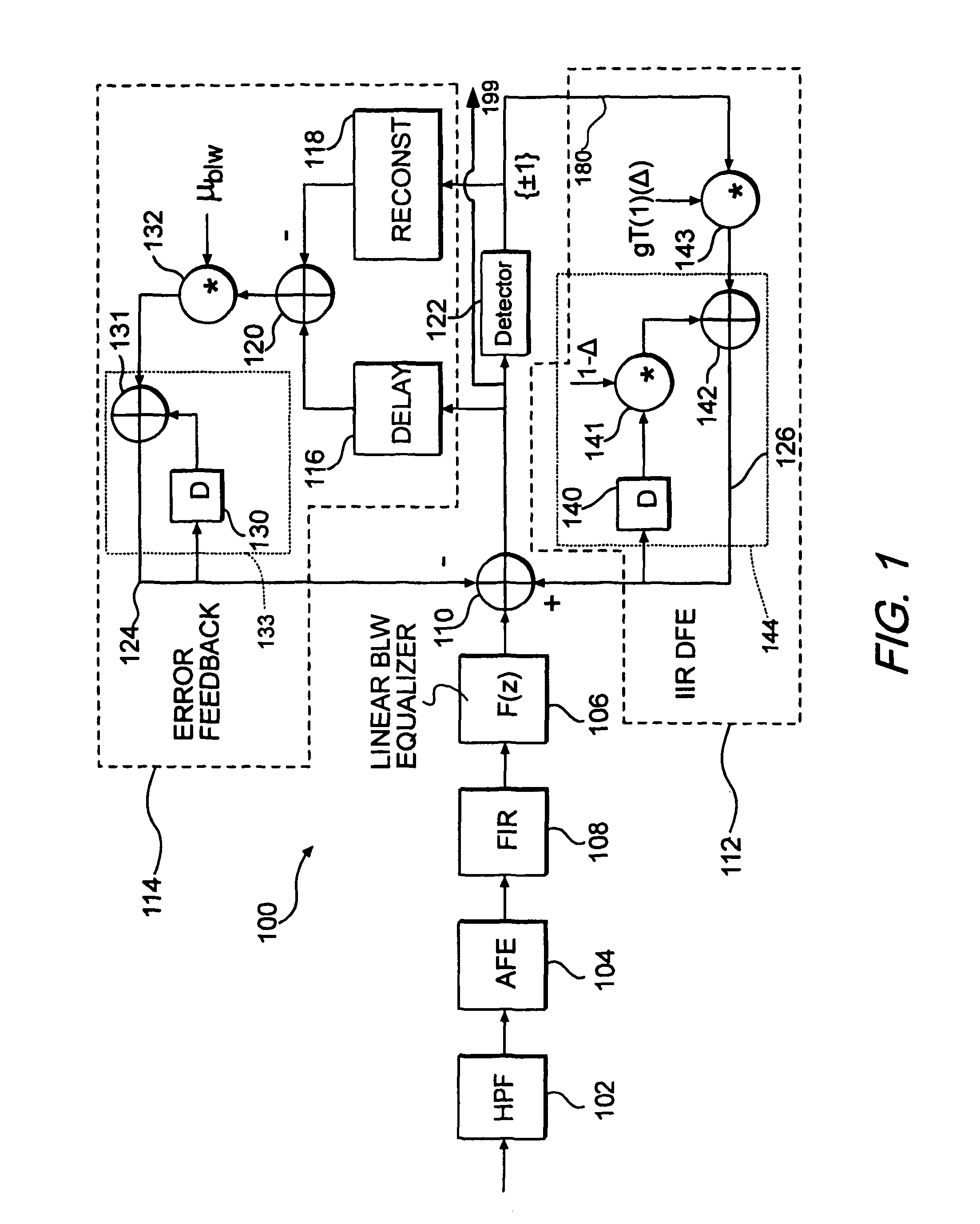
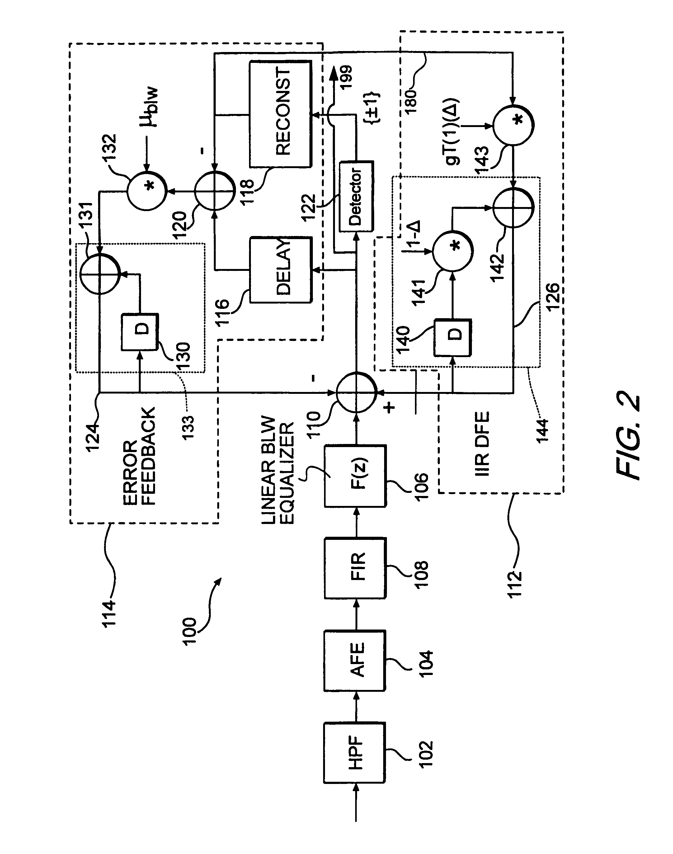
[0054]FIG. 2 shows the invention in which the detector 122, which again may be a sequence detector or more specifically a Viterbi device, is configured in a different manner. In the FIG. 2 embodiment, the output of the detector 122 is not directly input to the DFE filter 112 as in the FIG. 1 embodiment. Rather, the DFE filter 112 receives a signal from the error feedback component 114. More specifically, the output from the detector 122 is input to the reconstruction filter 118 and the output 181 of the reconstruction filter 118 is input to scaler 143, such as a multiplier of the DFE filter 112, which is fed back to the combiner 110 in a manner similar to FIG. 1. The output from reconstruction filter 118 of the error feedback component 114 also is combined with the output from delay 116 in the combiner 120, and the rest of the system operates similarly to the FIG. 1 embodiment.

[0055]FIG. 3 shows a feed forward filter 600 that may be used as the FIR filter 108. According to this embo...

third embodiment

[0057]FIG. 4 shows the invention 300 that is similar to the FIG. 2 embodiment, but includes a second pole configured to operate with another transfer function. In particular, all of the components except for DFE filter 312, which may be a feed forward infinite impulse response (IIR) DFE filter, operate similarly to the FIG. 2 implementation. In the FIG. 4 embodiment, the input to the DFE 312 is received from the reconstruction filter 118 similar to the FIG. 2 embodiment. However, in the FIG. 4 embodiment, the signal output from reconstruction filter 118 is input to a scaling device 346, such as a multiplier that may receive a scaling input of g1g2, where

[0058]gj=11+παj.

The scaler 346 then outputs to a scaler 347, such as a multiplier. The scaler 347 also may receive a scaling input signal of Δ1+Δ2. The scaler 346 also outputs to an integrator 382, which in this embodiment may include a delay blocks 348, 352, scalers 349, 351, and combiner 350 that integrate the received signal. The ...


PUM


Abstract

A method and device for compensating for undesirable signal characteristics such as baseline wander that includes a linear equalization filter responsive to receive an input, a combiner responsive to an output of the linear equalization filter, and a decision feedback equalization filter responsive to an output of the combiner, where the combiner is further responsive to an output of the decision feedback equalizer. Additionally, an error feedback circuit is responsive to the output of the combiner, and the combiner is further responsive to an output of the error feedback circuit to form a compensated signal having reduced distortion relative to the distorted signal.

Description

CROSS-REFERENCE TO RELATED APPLICATIONS[0001]This application is a continuation of U.S. patent application Ser. No. 10 / 053,885 filed on Jan. 16, 2002, and claims the benefit of U.S. Provisional Application No. 60 / 273,357, filed Mar. 5, 2001, both of which are hereby incorporated by reference in their entirety.[0002]This application claims priority under 35 U.S.C. §119(e) to provisional U.S. Patent Application No. 60 / 642,625, filed on Jan. 10, 2005, the disclosure of which is expressly incorporated by reference herein in its entirety, and this application claims priority under 35 U.S.C. 5119(e) to provisional U.S. Patent Application No. 60 / 736,306, filed on Nov. 15, 2005.BACKGROUND OF THE INVENTION[0003]1. Field of the Invention[0004]The invention is directed generally to compensating for undesirable characteristics in electronic signals, and, more particularly, to a method and device to compensate for baseline wander.[0005]2. Related Art[0006]In the past, baseline wander has not bee...

Claims


Application Information

Patent Timeline
Patent Type & Authority Patents(United States)
IPC IPC(8): H03H7/30H03K5/159H03H7/40
CPCH04L25/03057H04L25/06
Inventor ALTEKAR, SHIRISH
Owner MARVELL ASIA PTE LTD
Why Eureka
Try Eureka