
Device and method for controlling the temperature inside a refrigerating unit of a combined refrigerator-freezer

a technology of refrigerator freezer and refrigerating unit, which is applied in the direction of cooling fluid circulation, domestic applications, lighting and heating apparatus, etc., can solve the problems of inability to use the solution described above in the field of refrigerating unit of a combined refrigerator-freezer, inability to achieve the effect of facilitating air circulation

Inactive Publication Date: 2012-03-27
ITW IND COMPONENTS SRL
View PDF33 Cites 7 Cited by
  • Summary
  • Abstract
  • Description
  • Claims
  • Application Information

AI Technical Summary

Benefits of technology

This solution provides precise and energy-efficient temperature control in the above-zero unit, reducing food spoilage and energy waste, and can be applied to both ventilated and non-ventilated refrigerator-freezers, while being cost-effective and compact.

Problems solved by technology

The solution described above is not entirely satisfactory.
Indeed, an accurate temperature control, in particular in the above-zero unit, which is also the unit most frequently opened by the user, is not always optimal, which may also cause the early perishing of the foods conserved within.
Furthermore, the solution described above can in practice only be used in ventilated or “no-frost” refrigerators-freezers, in which the presence of the ventilator ensures the forced passage of air between the two refrigerating units.
Finally, the need of maintaining adequately cool the above-zero refrigerating unit, which is more frequently opened and which consequently “warms up” more frequently, forces to adopt a temperature control cycle which entails a high waste of energy.

Method used


Image

  • Device and method for controlling the temperature inside a refrigerating unit of a combined refrigerator-freezer
  • Device and method for controlling the temperature inside a refrigerating unit of a combined refrigerator-freezer

Examples


Embodiment Construction

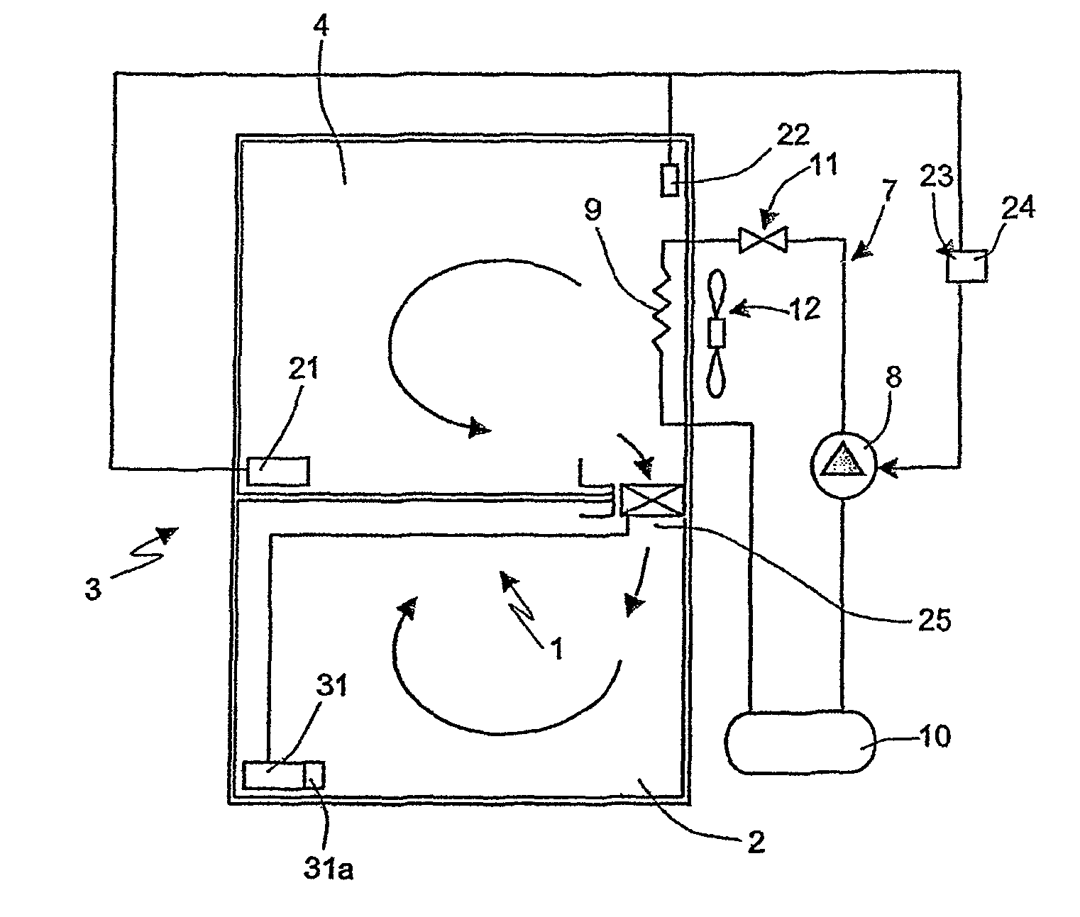
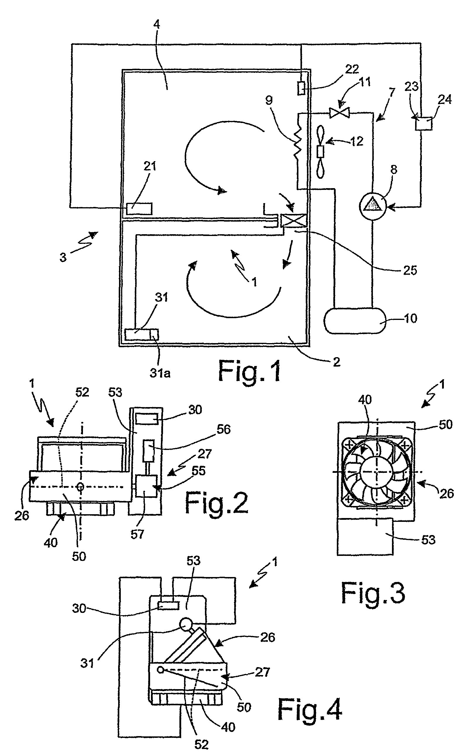
[0017]With reference to FIG. 1, it is indicated as a whole by 1 a control device of the temperature inside a refrigerating unit 2, in particular of a household appliance 3 of the combined type (refrigerator-freezer), provided with a second refrigerating unit 4; refrigerating means consisting of a cooling circuit 7 of the known type, comprising a compressor 8, an evaporator 9, a condenser or radiator 10 and an expansion valve 11, serving both refrigerating units 2 and 4; in particular, the evaporator 9 is arranged close to the refrigerating unit 4, intended in use to remain at sub-zero Centigrade temperatures (freezer unit). In order to prevent the formation of ice due to freezing of condensation, circuit 7 is provided with a defrosting ventilator 12 of the known type, arranged near the evaporator 9, in particular upstream of the same with respect to an air flow (indicated by the arrow in FIG. 1) which circulates in use in unit 4 during the ventilated (no-frost) cooling cycle.

[0018]T...


PUM


Abstract

A refrigerator-freezer of the combined type comprises a first and a second refrigerating units and a single cooling circuit for both units, which are fluid-dynamically and reciprocally connected by an air passage conduit; the temperature inside the first unit is controlled by a device comprising motorised interception means of the passage conduit; electronic control means of the motorised interception means, directly carried aboard a supporting body adapted in use to be arranged along the passage conduit; an electronic temperature sensor operatively and directly connected to the electronic control means, carried aboard the supporting body; and ventilator means, carried aboard the supporting body, operated by the electronic control means of the motorised interception means for selectively ensuring circulation of air by forced convection between the first and second refrigerating units along the passage conduit.

Description

RELATED APPLICATIONS[0001]The present application is based on International Application No. PCT / EP2006 / 062646 filed May 27, 2006 and claims priority from Italian Application Number TO2005A000361 filed May 27, 2005, the disclosures of which are hereby incorporated by reference herein in their entirety.TECHNICAL FIELD[0002]The present invention relates to a method and device for controlling the temperature inside a refrigerating unit of a refrigerator-freezer of the combined or two-door type, i.e. in which two reciprocally separate refrigerating units are present, one for the conservation of foods at sub-zero temperatures (freezer unit) and one for the conservation of foods at above-zero Centigrade temperatures (fresh food refrigerating unit) served by a single cooling circuit operated by a single compressor. The invention is particular useful for combined refrigerator-freezers of the ventilated type, also known as “no-frost” appliances, but also for static appliances.BACKGROUND ART[0...

Claims


Application Information

Patent Timeline
Patent Type & Authority Patents(United States)
IPC IPC(8): F25D17/06F25D17/08F25D17/04
CPCF25D17/045F25D17/065F25D2700/12F25D2400/04F25D2700/10F25D2317/0663F25D17/04
Inventor MALPETTI, ROBERTO
Owner ITW IND COMPONENTS SRL
Learn More