
Photography device and photography method

a technology of a camera and a lens, which is applied in the field of photography devices and photography methods, can solve the problems of difficult determining a viewing angle, photograph composition and the like, and large difference between the viewing angle to be photographed and a person's own field of view

Inactive Publication Date: 2012-03-27
FUJIFILM CORP
View PDF5 Cites 2 Cited by
  • Summary
  • Abstract
  • Description
  • Claims
  • Application Information

AI Technical Summary

Benefits of technology

The present invention provides a photography device and method that can assist a photographer in determining composition when altering the magnification ratio of a subject image and performing photography. The device includes an imaging component, focusing component, magnification alteration component, display component, acquisition component, control component, and storage component. The control component controls the imaging component to focus the subject image and acquires the image. The acquisition component divides the subject image into smaller parts and acquires a focusing evaluation value for each part. The control component then controls the display component to display the subject image in real-time based on the acquired focusing evaluation value. The invention can help a photographer quickly determine the composition of the subject image and make adjustments accordingly.

Problems solved by technology

When photography is performed using a high magnification zoom function, there is a large difference between the viewing angle to be photographed and a person's own field of view.
Consequently, determining a viewing angle, a photograph composition and the like may be difficult.
Thus, in an image obtained with high magnification zoom, if the user's composition technique or movement is even slightly misplaced, the viewing angle and composition are greatly misplaced.
However, the technologies of JP-A Nos. 2001-211360, 7-336569 and 5-130481 have a problem, are not being able to respond to a case of a large displacement from a subject image that is to be photographed.

Method used


Image

  • Photography device and photography method
  • Photography device and photography method
  • Photography device and photography method

Examples


first exemplary embodiment

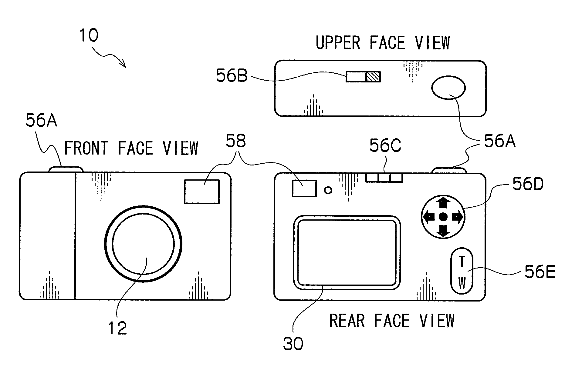
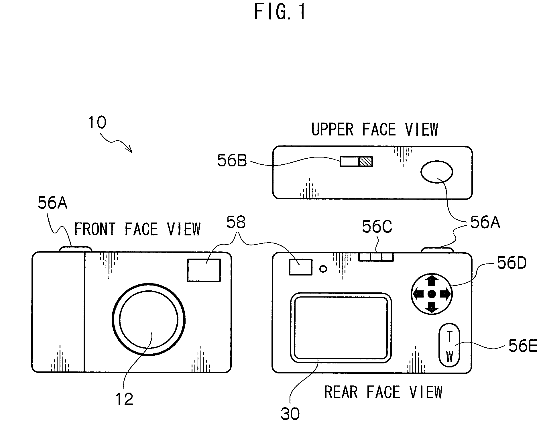
[0033]Firstly, external structures of a digital camera 10 relating to the first exemplary embodiment will be described with reference to FIG. 1. As is shown in FIG. 1, a lens 12, for focusing a subject image, and a viewfinder (an OVF, or optical viewfinder) 58, which is used for determining the composition of a subject to be photographed, are provided at the front face of the digital camera 10. A release button (“shutter”) 56A, which is pressed for operation by a photographer when photography is to be executed, and a power switch 56B are provided at an upper face of the digital camera 10.

[0034]The release button 56A relating to the present exemplary embodiment is constituted to be capable of detecting two stages of pressing operation: a state of being pressed down to an intermediate position (herebelow referred to as a half-pressed state) and a state of being pressed down beyond the intermediate position to a final lowermost position (below referred to as a full-pressed state).

[0035...

second exemplary embodiment

[0078]For the first exemplary embodiment, a mode has been described in which the zoom ratio is lowered if the AF evaluation value when the image contrast is maximized falls to or below the predetermined threshold value Th. For the second exemplary embodiment, a mode will be described in which the zoom ratio is lowered if a comparison value, which is calculated on the basis of AF evaluation values that correspond to a predetermined interval between images acquired via the CCD 14, is at or below a predetermined threshold value.

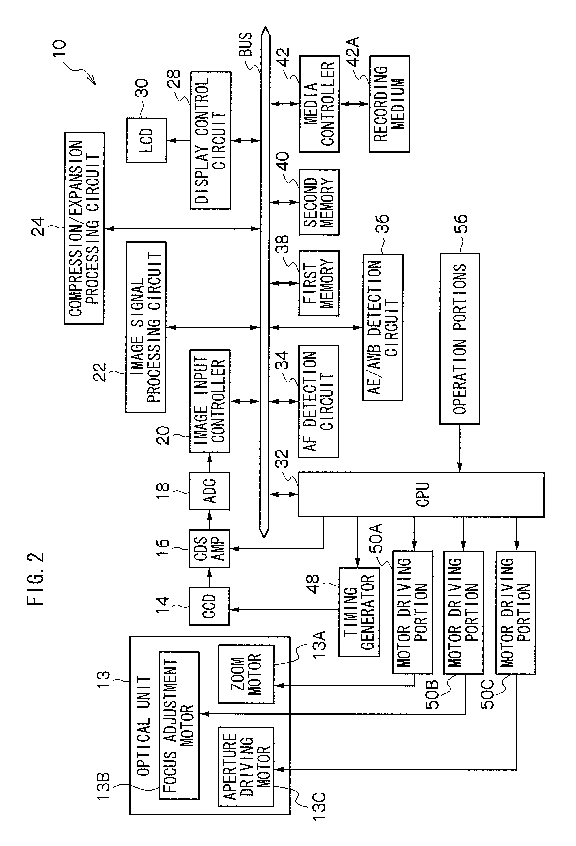
[0079]The structure of a digital camera relating to this second exemplary embodiment is similar to the structure of the digital camera 10 described in the first exemplary embodiment (see FIG. 1 and FIG. 2), and only the details of the photography processing differ. Herebelow therefore, the same reference numerals are assigned to the same structures and descriptions thereof are not given. Details of the photography processing are described with reference to the d...

third exemplary embodiment

[0095]For the first exemplary embodiment and the second exemplary embodiment, modes have been described in which the zoom ratio is lowered in accordance with AF evaluation values at which image contrast is maximized. For the third exemplary embodiment, a mode will be described in which, in accordance with change amounts of AF evaluation values of division regions, a display of advice that shows a direction to a subject image to a user is implemented.

[0096]The structure of a digital camera relating to this third exemplary embodiment is similar to the structure of the digital camera 10 described in the first exemplary embodiment (see FIG. 1 and FIG. 2), and only the details of the photography processing differ. Herebelow therefore, the same reference numerals are assigned to the same structures and descriptions thereof are not given. Details of the photography processing are described with reference to the drawings.

[0097]FIG. 9A and FIG. 9B are a flowchart showing a flow of a photogra...


PUM


Abstract

A photography device that includes an imaging component, a focusing component, a magnification alteration component, a display component, an acquisition component and a control component is provided. The focusing component focuses a subject image on an imaging surface of the imaging component. The magnification alteration component alters a magnification of the subject image focused by the focusing component. The acquisition component acquires a focusing evaluation value representing a degree of focusing of the subject image by the focusing component. The control component performs focusing control by controlling the focusing component such that the focusing evaluation value acquired by the acquisition component is at a maximum, and controls the magnification alteration component so as to lower a display magnification of the subject image by the display component if the focusing evaluation value is at or below a pre-specified threshold value.

Description

CROSS-REFERENCE TO RELATED APPLICATION[0001]This application claims priority under 35 USC 119 from Japanese Patent Application No. 2008-068362, the disclosure of which is incorporated by reference herein.BACKGROUND OF THE INVENTION[0002]1. Field of the Invention[0003]The present invention relates to a photography device and photography method that acquire image information representing a subject image by photography.[0004]2. Description of the Related Art[0005]Heretofore, it has been proposed that cameras be provided with magnifying zoom functions, which magnify subject images that are photographed. In recent years, installation of high magnification zoom functions even in compact cameras has been desired.[0006]When photography is performed using a high magnification zoom function, there is a large difference between the viewing angle to be photographed and a person's own field of view. Consequently, determining a viewing angle, a photograph composition and the like may be difficult...

Claims


Application Information

Patent Timeline
Patent Type & Authority Patents(United States)
IPC IPC(8): G03B17/00
CPCH04N5/23212H04N5/23293H04N5/23296H04N23/673H04N23/633H04N23/69
Inventor SHIKATA, DAISUKE
Owner FUJIFILM CORP
Learn More