Fuel nozzle providing shaped fuel spray

a fuel nozzle and nozzle technology, applied in the direction of burners, combustion chambers, combustion processes, etc., can solve the problems of requiring a relative large number of fuel nozzles about the combustor, and no alternative for controlling the density and profile of the fuel spray in the combustor, so as to achieve the effect of improving the fuel nozzl

Active Publication Date: 2012-04-03
PRATT & WHITNEY CANADA CORP
View PDF68 Cites 36 Cited by
  • Summary
  • Abstract
  • Description
  • Claims
  • Application Information

AI Technical Summary

Problems solved by technology

However, in order to achieve a complete fuel spray coverage in annular combustors, a relatively large number of fuel nozzles are required about the combustor.
Further, as the overall shape of the fuel spray produced is fixed, no alternatives exist for controlling the density and profile of fuel sprays in the combustor.

Method used


Image

  • Fuel nozzle providing shaped fuel spray
  • Fuel nozzle providing shaped fuel spray
  • Fuel nozzle providing shaped fuel spray

Examples


Embodiment Construction

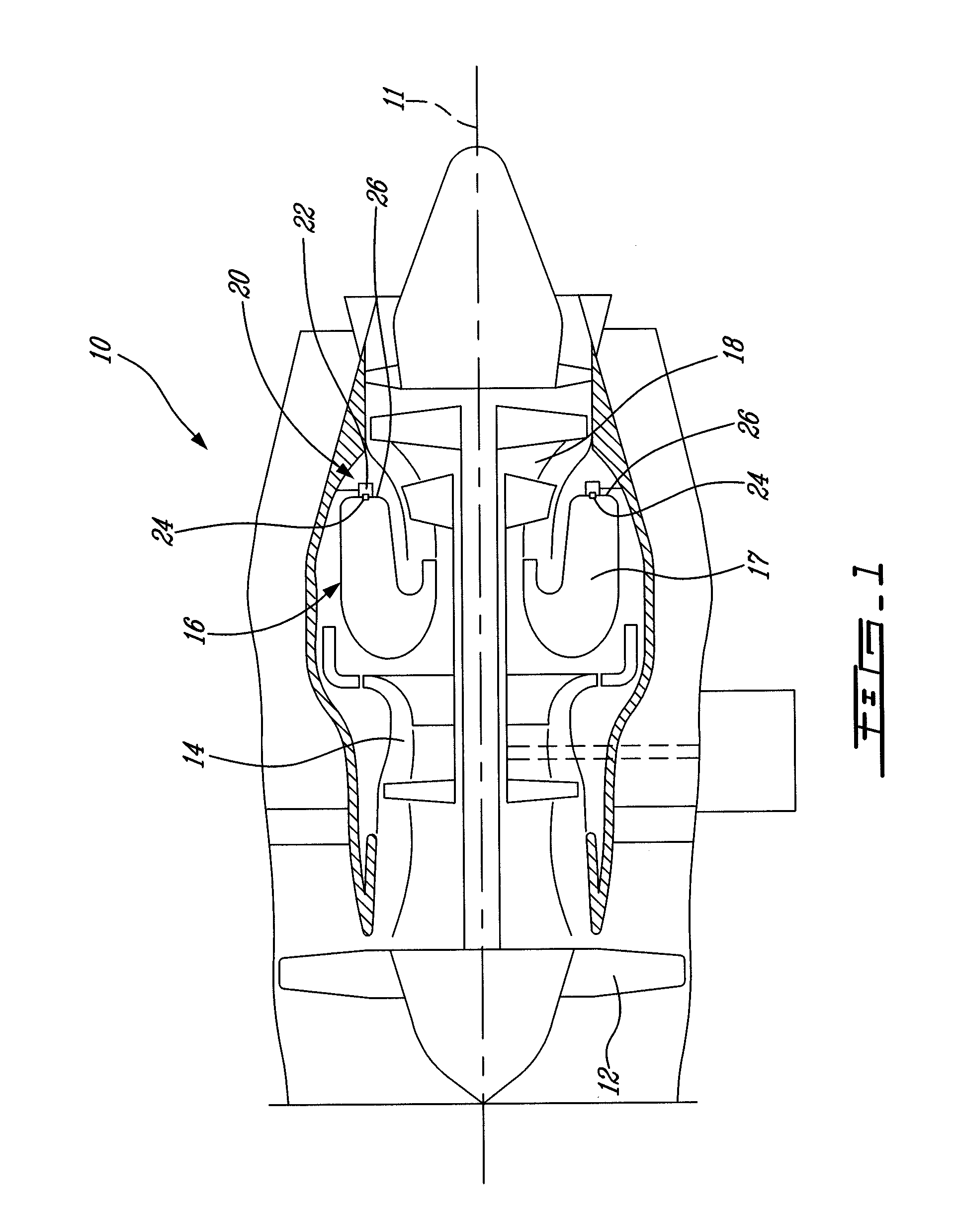
[0020]FIG. 1 illustrates a gas turbine engine 10 of a type preferably provided for use in subsonic flight, generally comprising in serial flow communication a fan 12 through which ambient air is propelled, a multistage compressor 14 for pressurizing the air, a combustor 16 in which the compressed air is mixed with fuel and ignited for generating an annular stream of hot combustion gases, and a turbine section 18 for extracting energy from the combustion gases.

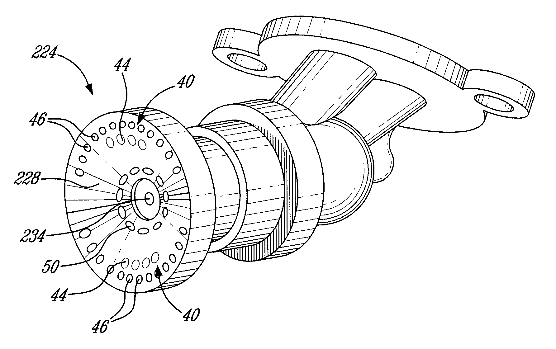
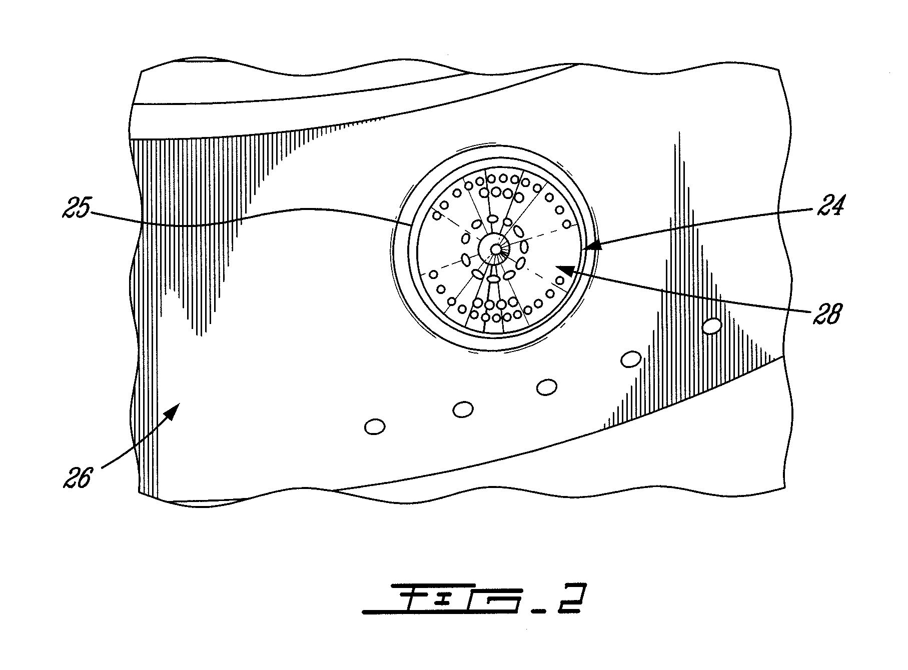
[0021]Fuel is injected into the combustor 16 of the gas turbine engine 10 by a fuel injection system 20, which includes a fuel source (not shown), at least one fuel conveying assembly or internal fuel manifold 22 and a number of fuel nozzles 24 engaged with the fuel manifold and which are operable to inject fuel into the combustor 16 for mixing with the compressed air from the compressor 14 and ignition of the resultant mixture. The fan 12, compressor 14, combustor 16, and turbine 18 are preferably all concentric about a common...


PUM


Abstract

A fuel injection nozzle for a gas turbine engine has a central fuel ejection nozzle and a plurality of airflow passages within the spray tip that include a first and second group of circumferentially spaced apart fuel-spray forming airflow passages disposed on opposite sides of a transverse axis and oriented towards each other such as to produce opposed fuel spray shaping air jets which generate a shaped final fuel spray.

Description

TECHNICAL FIELD[0001]The invention relates generally to gas turbine engines and, more particularly, to fuel nozzles for such engines.BACKGROUND OF THE ART[0002]Gas turbine engine combustors employ a plurality of fuel nozzles, typically arranged in an annular configuration, to spray the fuel into the combustion chamber of an annular combustor. Each of these fuel nozzles generates a spray of fuel which is generally conical in shape and which defines a generally circular cross-sectional profile, as shown in FIG. 6b for example. However, in order to achieve a complete fuel spray coverage in annular combustors, a relatively large number of fuel nozzles are required about the combustor. Further, as the overall shape of the fuel spray produced is fixed, no alternatives exist for controlling the density and profile of fuel sprays in the combustor.[0003]Accordingly, there is a need for an improved fuel nozzle for a gas turbine engine combustor which permits, inter alia, a reduction in the to...

Claims


Application Information

Patent Timeline
Patent Type & Authority Patents(United States)
IPC IPC(8): F23R3/14F23R3/50
CPCF23D11/108F23D11/12F23D11/24F23R3/10F23R3/28
Inventor SHUM, FRANKVERHIEL, JEFFREY
Owner PRATT & WHITNEY CANADA CORP
Why Eureka
Try Eureka