Eureka AIR delivers breakthrough ideas for toughest innovation challenges, trusted by R&D personnel around the world.

Turbine drive system with lock-up clutch and method

a technology of clutch and turbine engine, which is applied in the direction of engine starter, turbine/propulsion engine ignition, machines/engines, etc., can solve the problems of engine not being able to keep up with the generator load, engine may be required to run at high core speed and surge bleed to reduce engine thrust,

Inactive Publication Date: 2012-04-03
HONEYWELL INT INC
View PDF31 Cites 39 Cited by
  • Summary
  • Abstract
  • Description
  • Claims
  • Application Information

AI Technical Summary

Problems solved by technology

As a result, the engine may not be able to keep up with the generator load demand at various low thrust conditions in the flight envelope.
As a result, the engine may be required to run at high core speeds and surge bleed to reduce engine thrust.
The system should not significantly reduce engine efficiency, and / or significantly increase fuel consumption, and / or increase overall operational costs.

Method used


Image

  • Turbine drive system with lock-up clutch and method
  • Turbine drive system with lock-up clutch and method

Examples


Embodiment Construction

[0015]Before proceeding with the detailed description, it is to be appreciated that the following detailed description is merely exemplary in nature and is not intended to limit the invention or the application and uses of the invention. In this regard, it is to be additionally appreciated that the described embodiment is not limited to use in conjunction with a particular type of turbine engine. Hence, although the present embodiment is, for convenience of explanation, depicted and described as being implemented in a multi-spool gas turbine jet engine, it will be appreciated that it can be implemented in various other types of turbines, and in various other systems and environments. Furthermore, there is no intention to be bound by any theory presented in the preceding background or the following detailed description.

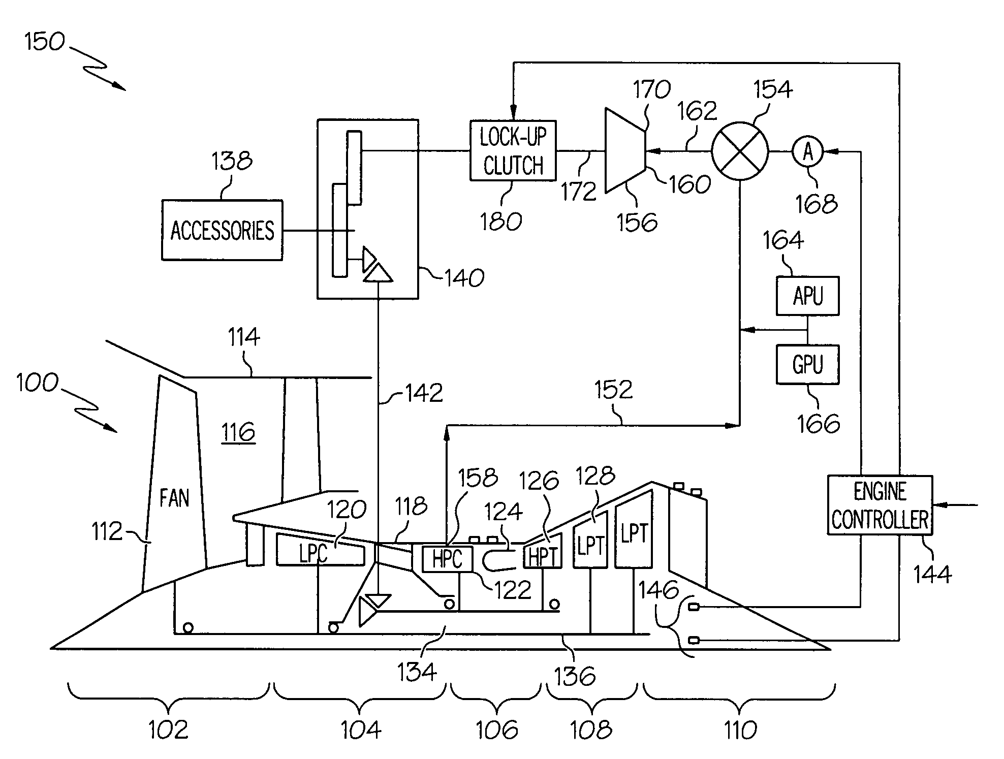
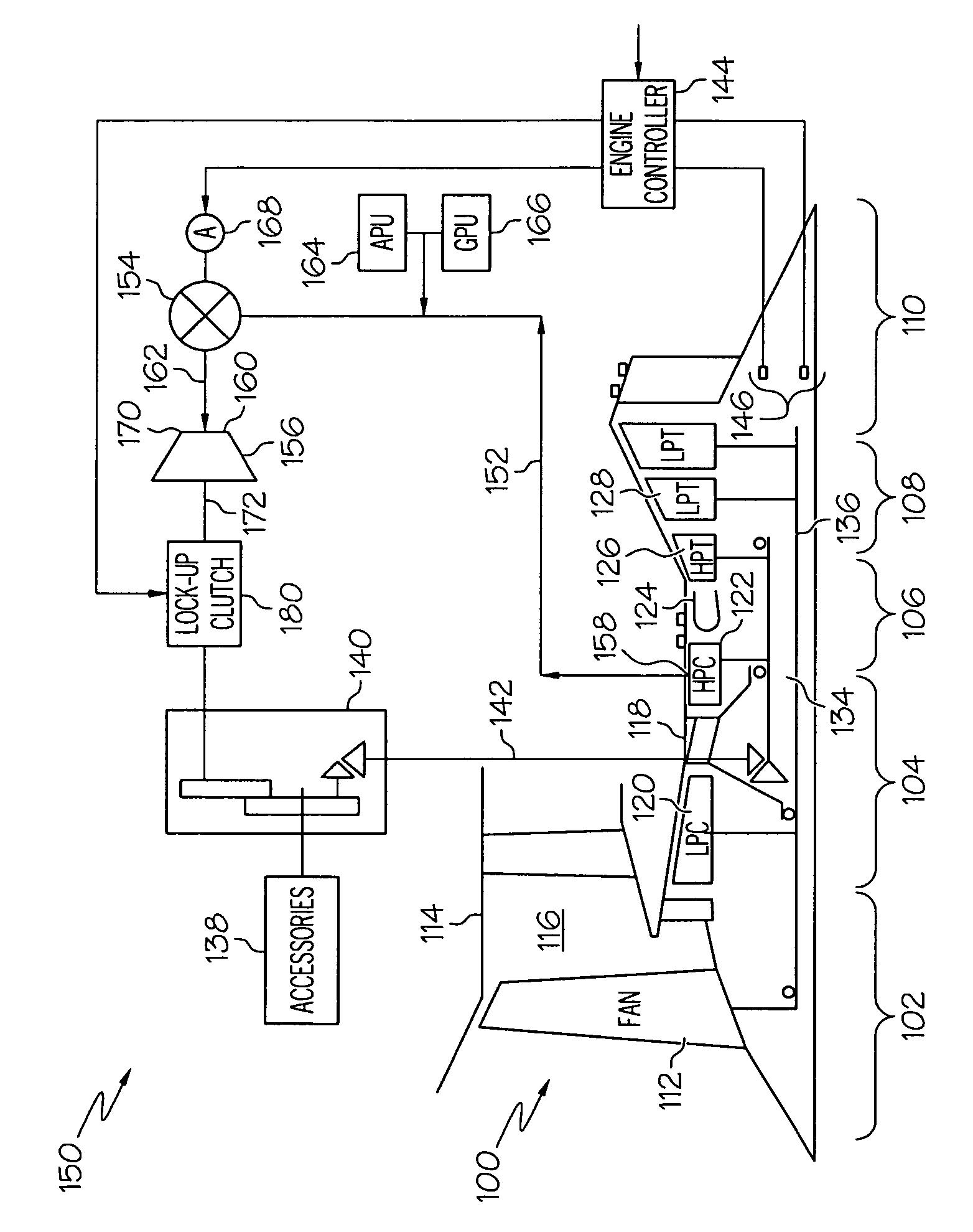
[0016]A simplified representation of an exemplary multi-spool turbofan gas turbine jet engine 100 is depicted in FIG. 1, and includes an intake section 102, a compress...


PUM


Abstract

A pneumatically driven turbine drive system is coupled to a gas turbine engine that includes low and high pressure compressors, low and high pressure turbines, a lock-up clutch, and at least one engine accessory driven by the high pressure compressor. The pneumatically driven turbine drive system selectively bleeds air discharged from the high pressure compressor and supplies it to an air turbine that is coupled to the at least one engine accessory. Thus, the system selectively reduces the power extracted from the high pressure compressor and is capable of supplying power back to the engine core. This, coupled with the bleed air that is diverted from the high pressure turbine and the low pressure turbine, allows the high pressure spool and the low pressure spool to run at lower speeds when high engine thrust is not needed or desired, but when the at least one engine accessory is still needed.

Description

TECHNICAL FIELD[0001]The present invention relates to gas turbine engines and, more particularly, to a gas turbine engine drive system including a lock-up clutch and method for extracting fluid power from the gas turbine engine and converting it to mechanical power in a gearbox.BACKGROUND[0002]A gas turbine engine may be used to supply power to various types of vehicles and systems. For example, gas turbine engines may be used to supply propulsion power to an aircraft. Many gas turbine engines include at least three major sections, a compressor section, a combustor section, and a turbine section. The compressor section receives a flow of intake air and raises the pressure of this air to a relatively high level. In a multi-spool (e.g., multi-shaft) engine, the compressor section may include two or more compressors. The compressed air from the compressor section then enters the combustor section, where a ring of fuel nozzles injects a steady stream of fuel. The injected fuel is ignite...

Claims


Application Information

Patent Timeline
Patent Type & Authority Patents(United States)
IPC IPC(8): F02C3/10F02C6/00
CPCF02C3/10F02C7/32F02C9/18Y02T50/671Y02T50/60
Inventor ZEINER, PETER KENNETHLIBERA, TONYLANGSTON, TODD
Owner HONEYWELL INT INC
Why Eureka
Eureka Blog
Learn More