Multifunctional detonation system

a detonation system and multi-functional technology, applied in the field of explosion devices, can solve the problems of insufficiently achieving the desired explosive effect, difficult assembly of explosive devices in situ, and high probability of errors in procedures,

Active Publication Date: 2012-04-03
RECCONN
View PDF11 Cites 1 Cited by
  • Summary
  • Abstract
  • Description
  • Claims
  • Application Information

AI Technical Summary

Benefits of technology

[0037]A kit according to Claim 19 for an explosive apparatus according to the invention contains a basic module and at least one additional module. The modular design allows the strength of the explosive charge to be varied within wide limits, and therefore to be matched to the intended target.

Problems solved by technology

The latter in particular are subject to various disadvantages, in particular relating to achievement of the desired explosive effect.
The explosive apparatus must be assembled in situ, which is difficult.
Since this is often subject to time pressures, this procedure is highly susceptible to errors.
In consequence, the desired explosive effect is achieved only inadequately, or not at all.
In the case of improvised explosive charges, the unprotected fuze is often also damaged, thus in the end rendering the entire explosive apparatus unusable.

Method used


Image

  • Multifunctional detonation system
  • Multifunctional detonation system
  • Multifunctional detonation system

Examples


Embodiment Construction

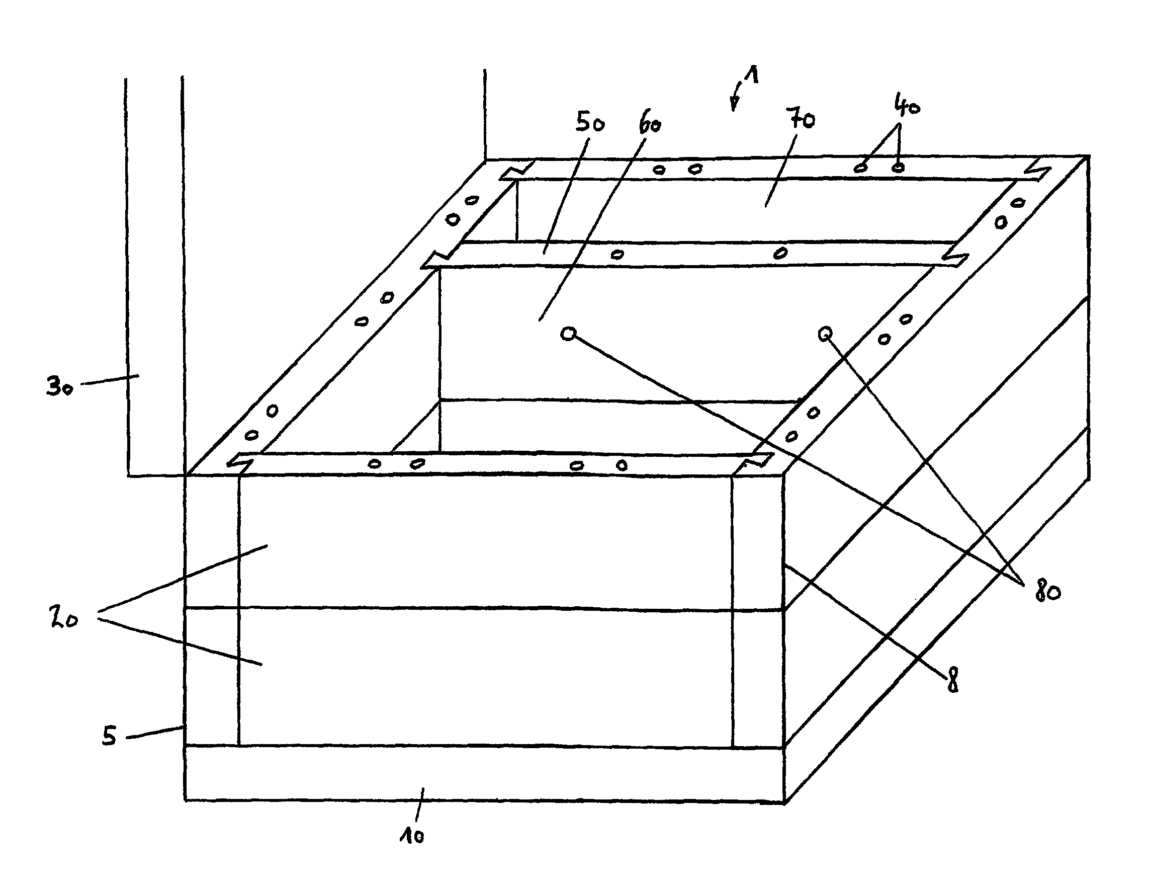
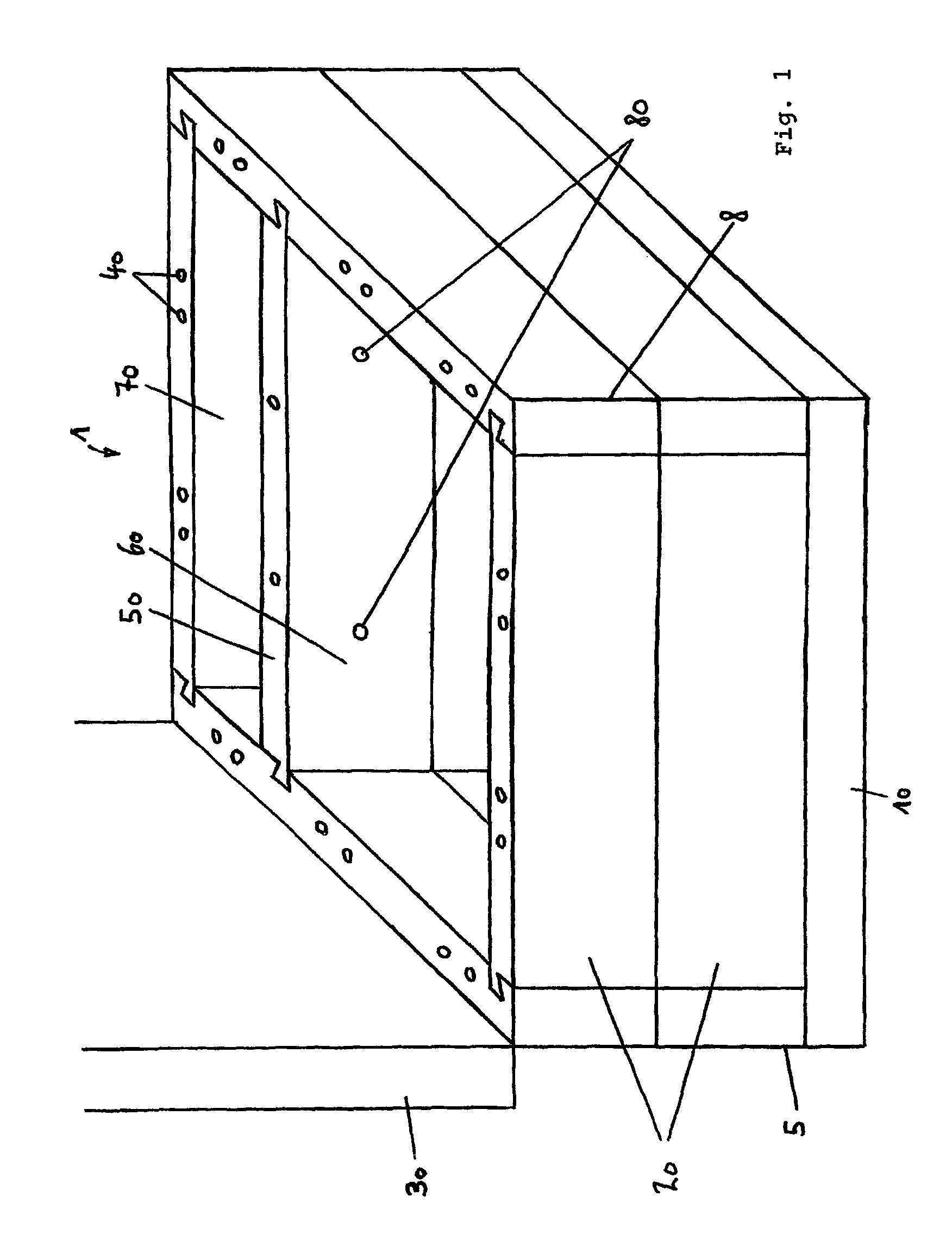
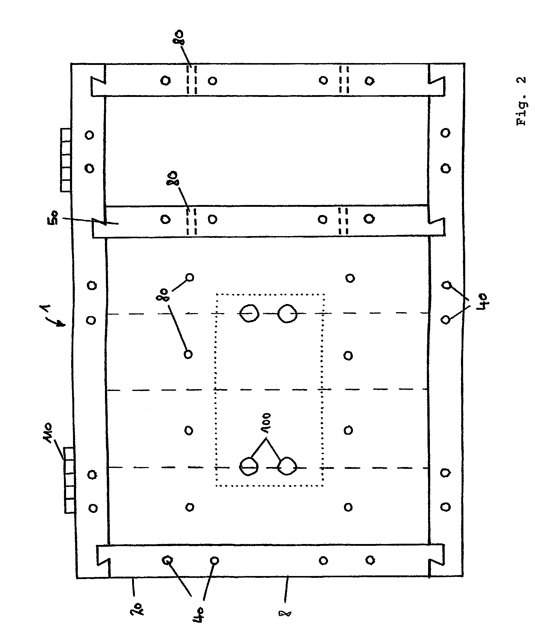
[0055]FIG. 1 shows a container 1 according to the invention with a rectangular bottom wall 10, side walls 20 and an open cover wall 30. The illustrated container 1 comprises a basic module 5 and an additional module 8. The height of the side walls 20 of the basic module 5 and of the side walls 20 of the additional module 8 corresponds to the shortest edge length of the molding 120. The basic module has a bottom wall 10, and side walls 20. The additional module has side walls 20, with the cover wall 30, which is part of the basic module, being attached to the additional module. The side walls 20 have threaded holes 40 through them and are preferably screwed tight against the bottom wall 10 by means of screws. An intermediate wall 50 separates an internal area 60, which is intended to accommodate moldings 120 as shown in FIG. 5 and as described further below, from a service area 70. The intermediate wall 50 also has aperture holes 80 through which an explosive capsule can be inserted ...


PUM


Abstract

Explosive apparatus has at least two cuboid moldings, which each includes at least one firing hole and explosive, and whose edge lengths have a ratio of substantially 1:2:4, and a container including an internal area having a square outline and at least one aperture hole to the internal area, the internal area having a side length corresponding at least approximately to a longest edge length of the moldings and a height corresponding at least approximately to a shortest edge length of the moldings or to an integer multiple thereof, wherein the moldings are placed in the internal area of the container such that the at least one firing hole in one of the at least two moldings is aligned with the at least one aperture hole in the container, the aperture hole being intended for insertion of an explosive capsule into the firing hole of the corresponding molding.

Description

BACKGROUND OF THE INVENTION[0001]1. Field of the Invention[0002]The present invention relates to an explosive apparatus, and to a container and a molding therefor.[0003]2. Discussion of Related Art[0004]Explosive apparatuses can be roughly subdivided into two types. On the one hand, those explosive apparatuses which are intended for a very specific purpose and are also suitable only for this purpose. On the other hand, those explosive apparatuses which are intended to be widely used and must therefore be matched to the specific circumstances for the specific application. The latter in particular are subject to various disadvantages, in particular relating to achievement of the desired explosive effect.[0005]Examples of explosive apparatuses having a specific purpose are shaped charges and directional charges.[0006]Shaped charges comprise a so-called hollow charge which allows the explosive hole that is required for the actual explosive charge to be prepared in the background. This c...

Claims


Application Information

Patent Timeline
Patent Type & Authority Patents(United States)
IPC IPC(8): F42B3/02
CPCF42B3/02F42B39/00
Inventor FRIEDEN, ERNEST
Owner RECCONN
Why Eureka
Try Eureka