Sealing cover for containers

a container and sealing technology, applied in the field of sealing covers, can solve the problems of difficult to maintain the integrity of the container opening b>10/b>, the latch ledges are prone to break or fracture, and the opening of the container is not operable single-handed

Active Publication Date: 2012-04-03
IDEARITE HLDG PTE LTD
View PDF6 Cites 8 Cited by
  • Summary
  • Abstract
  • Description
  • Claims
  • Application Information

AI Technical Summary

Benefits of technology

[0009]The primary object of the present invention is to provide a sealing cover to be used on a container without the need of providing jutting anchor portions thereon. Sealing elements also do not need air vents. It can form a sealed condition for containers with any shape of opening. The sealing effect is more secured. The shape of the container opening also can be maintained intact. When in use there is no alignment problem, thus is more convenient.
[0010]Another object of the invention is to provide a sealing cover that also can provide vacuuming function. Through a vacuum means the air in the container can be drawn out to form a vacuum condition in the interior. The invention also provides a double seal ring design to make sealing effect more secured to maintain the vacuum condition in the container. Therefore goods held in the container have a longer preservation period.
[0015]In yet another aspect the air permeable parasol valve provides air discharge function to facilitate capping of the cover on the container opening. And an air suction means can be disposed to draw the air in the container through the air permeable parasol valve to vacuum the interior of the container. Through the first seal ring a secured sealing effect can be achieved without the concern of deformation that might occur to the second seal ring. And the vacuum condition in the container can be maintained securely by the cover.
[0019]By means of the construction set forth above, the invention provides at least the following advantages: through the double sealing structure of two blade types seal rings the exterior of the container does not have to provide jutting means for anchoring, and there is no restriction on the shape of the container opening; no alignment for coupling is needed when in use; and operation is easier. Through the air permeable parasol valve which can release air, no air vent is required on the seal rings. Thus an improved sealing effect can be achieved. Through the air permeable parasol valve the air in the container can be drawn out through an air suction means to form a vacuum condition in the container.
[0020]In addition, as the second seal ring squeezed between the annular jutting portion and the inner wall of the container might be deformed after vacuuming and result in air leakage, the first seal ring can provide a more secured sealing effect due to a tighter compression between the cover and the container after vacuuming. Hence any gap that might occur between the annular jutting portion and the inner wall of the container and due to thickness accuracy of the second seal ring does not make significant impact to the overall sealing effect. Hence the problem of air leakage resulting from the second seal ring after vacuuming can be overcome. Fabrication also is simpler.

Problems solved by technology

However, after repetitive latching and rotating when in use for a period of time, the latch ledges 21 are prone to break or fracture at the joined locations.
It also is not operable single-handed.
Moreover, the design of the anchor portions 12 makes the opening of the container 10 difficult to maintain a desired integrity.
It is not convenient in practice.
Moreover, the sealing covers previously discussed provide only sealing function, but do not provide vacuuming function for the interior of the container.

Method used


Image

  • Sealing cover for containers
  • Sealing cover for containers
  • Sealing cover for containers

Examples


Embodiment Construction

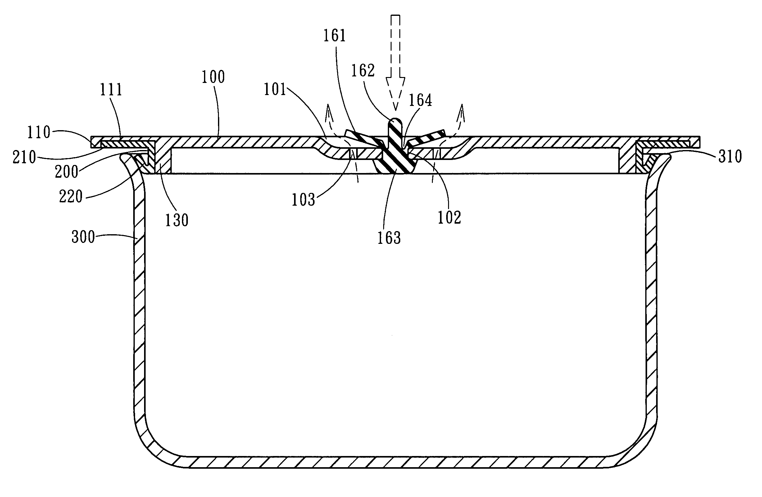
[0031]Please refer to FIGS. 3, 4 and 7, the sealing cover according to the invention aims to be used on a cover 100 to seal a container 300. The cover 100 includes features as follow: an annular jutting portion 130 located at a lower side thereof to be coupled with an opening of the container 300. The annular jutting portion 130 has a top coupling portion 110 on the periphery that further is extended to form a moving flange 120 at a selected location to facilitate moving upward of the cover 100 to be separated from the opening of the container 300.

[0032]The annular jutting portion 130 is surrounded by a seal ring 200 at an outer side. The seal ring 200 has two blade type rings extended outwards including a first seal ring 210 and a second seal ring 220. The first seal ring 210 is fastened to the surface of the top coupling portion 110 and the second seal ring 220 is close to a top end of the annular jutting portion 130 (also referring to FIG. 5). In practice the top coupling portion...


PUM


Abstract

A sealing cover includes a cover coupling with a seal ring which has two blades to form a double sealing effect. Thus a container can be sealed by the cover more securely and the opening of the container can be maintained intact. The cover also has a coupling opening and a plurality of air vents. The coupling opening is coupled with an air permeable parasol valve which can release air to facilitate capping of the cover on the opening of the container. Through an air suction means the container can be vacuumed.

Description

CROSS REFERENCE TO RELATED APPLICATIONS[0001]This is a National Phase Application in the United States of International Patent Application No. PCT / CN2007 / 001937 filed on Jun. 20, 2007 in China. The entire disclosures of the above patent applications are hereby incorporated by reference.FIELD OF THE INVENTION[0002]The present invention relates to a sealing cover and particularly to a sealing cover that is simply structured and adaptable to be used on containers formed in various shapes and made from different materials and is vacuum-enabled.BACKGROUND OF THE INVENTION[0003]A conventional sealing cover adopted for use on containers of varying openings, such as an example of a container 10 shown in FIG. 1 that has a round opening, mainly includes a cover 20 to cap a top rim 11 at the opening of the container 10. The cover 20 has an annular groove 23 at a location in contact with the top rim 11. A sealing pad 24 is provided in the groove 23. When the top rim 11 is wedged in the groove 2...

Claims


Application Information

Patent Timeline
Patent Type & Authority Patents(United States)
IPC IPC(8): B65D51/16B65D43/04B65D53/00B65D41/56
CPCB65D43/022B65D51/1683B65D53/02B65D2543/00203B65D2543/00564B65D2543/00842
Inventor CHEN, HSIN-YU
Owner IDEARITE HLDG PTE LTD
Why Eureka
Try Eureka