Telescoping support stand apparatus

Active Publication Date: 2012-04-03
BUSHNELL HLDG
View PDF199 Cites 38 Cited by
  • Summary
  • Abstract
  • Description
  • Claims
  • Application Information

AI Technical Summary

Benefits of technology

[0027]According to at least one embodiment, a telescoping support stand may comprise a first tube partially defining a first enclosed area, a second tube partially defining a second enclosed area, and a third tube partially defining a third enclosed area. A first end of the first tube may be telescopically slidable within the second tube, and a first end of the second tube may be telescopically slidable within the third tube. A first locking mechanism may be attached to the first tube, and the first locking mechanism may releasably secure the first tube to the second tube to prevent longitudinal movem

Problems solved by technology

One problem with these types of locks is the time it takes for a user to turn the collar or bolt when making a height adjustment to the stand.
Another problem with these locks is that the user may have to hold the inner tube in position while fastening the lock, thus requiring the use of two hands.
While there are many benefits to a quick-adjustment configuration that utilizes an internal locking mechanism and a handle trigger, there are numerous problems associated with such a support stand configuration.
Thus, air cannot easily flow into, out of, or between the tubes of rugged support stands with internal locks.
When air is unable to quickly enter, exit, or flow between the tubes of a support stand, it is more difficult to make rapid height adjustments to the stand.
For example, when a user attempts to extend the length of the stand, the volume in

Method used


Image

  • Telescoping support stand apparatus
  • Telescoping support stand apparatus
  • Telescoping support stand apparatus

Examples


Embodiment Construction

[0068]Throughout the drawings identical reference characters and descriptions indicate similar, but not necessarily identical, elements. While embodiments of the instant disclosure are susceptible to various modifications and alternative forms, specific embodiments have been shown by way of example in the drawings and will be described in detail herein. However, one of skill in the art will understand that embodiments of the instant disclosure are not intended to be limited to the particular forms disclosed herein. Rather, the instant disclosure covers all modifications, equivalents, and alternatives falling within the scope of embodiments defined by the appended claims.

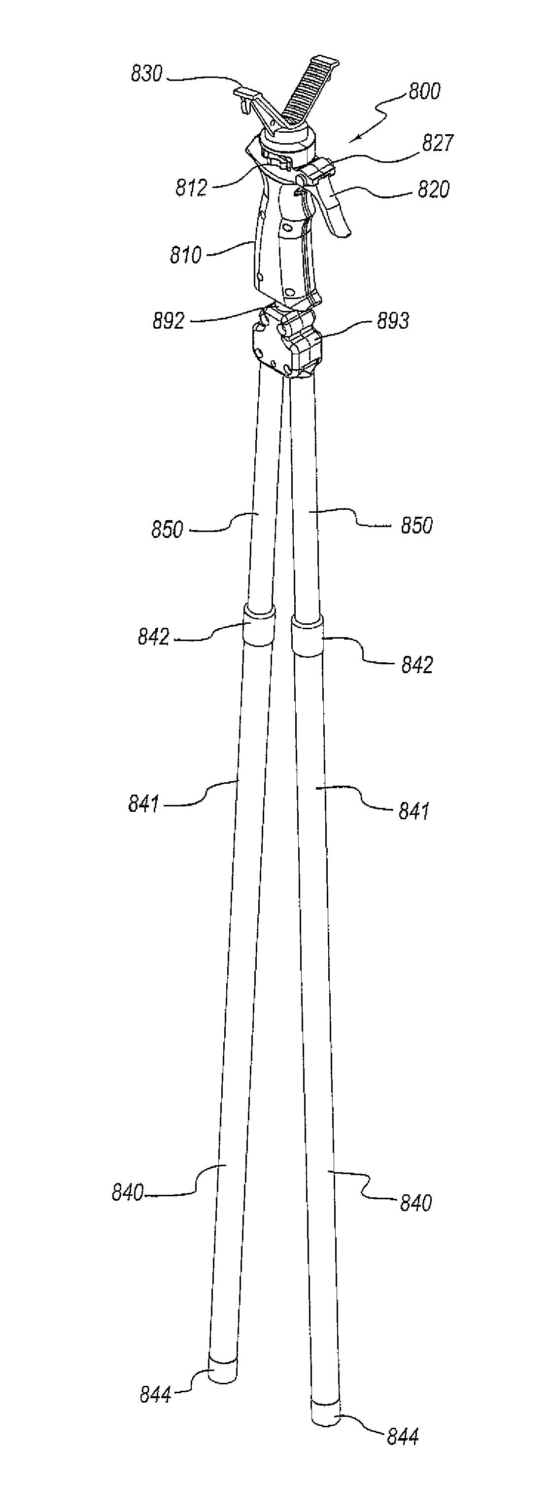
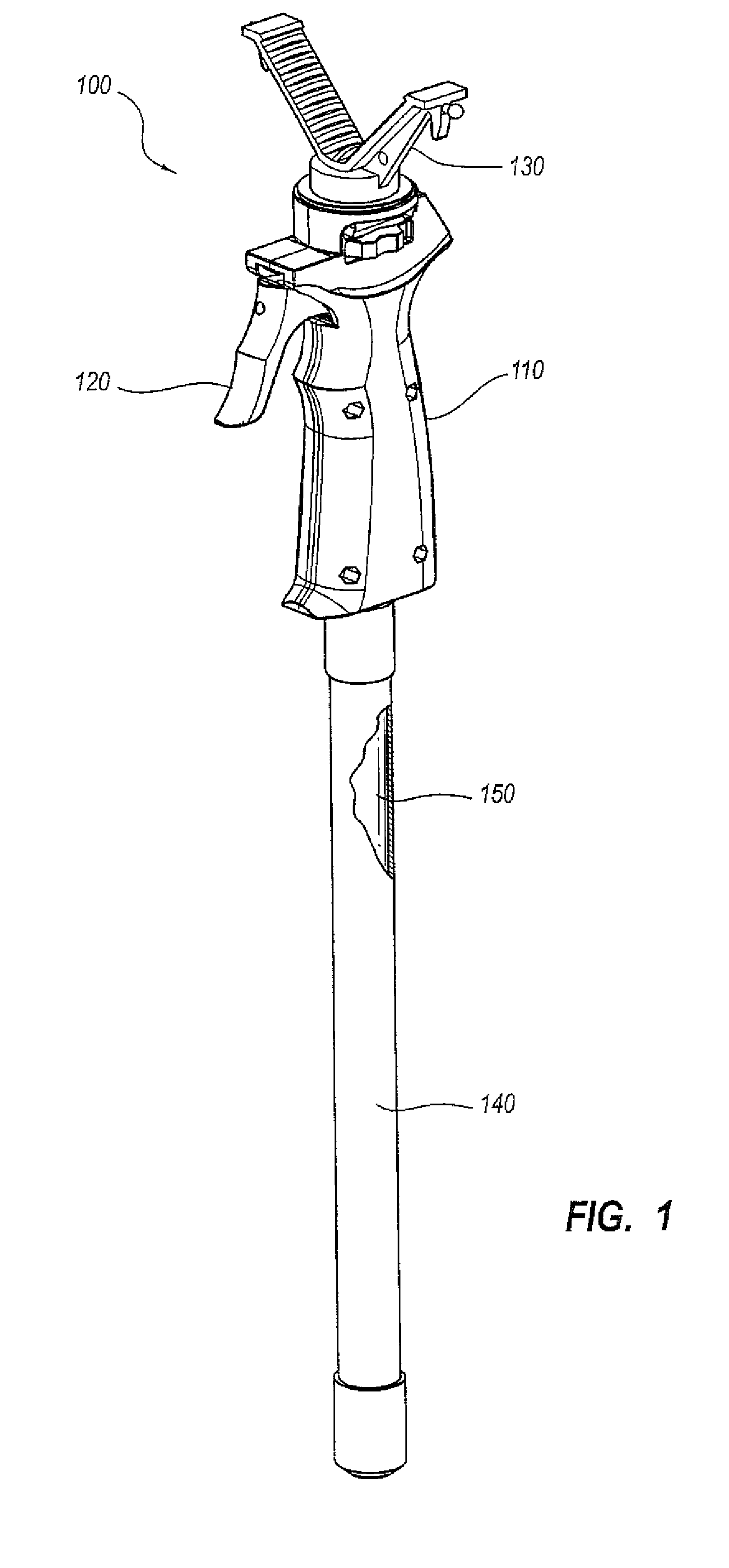
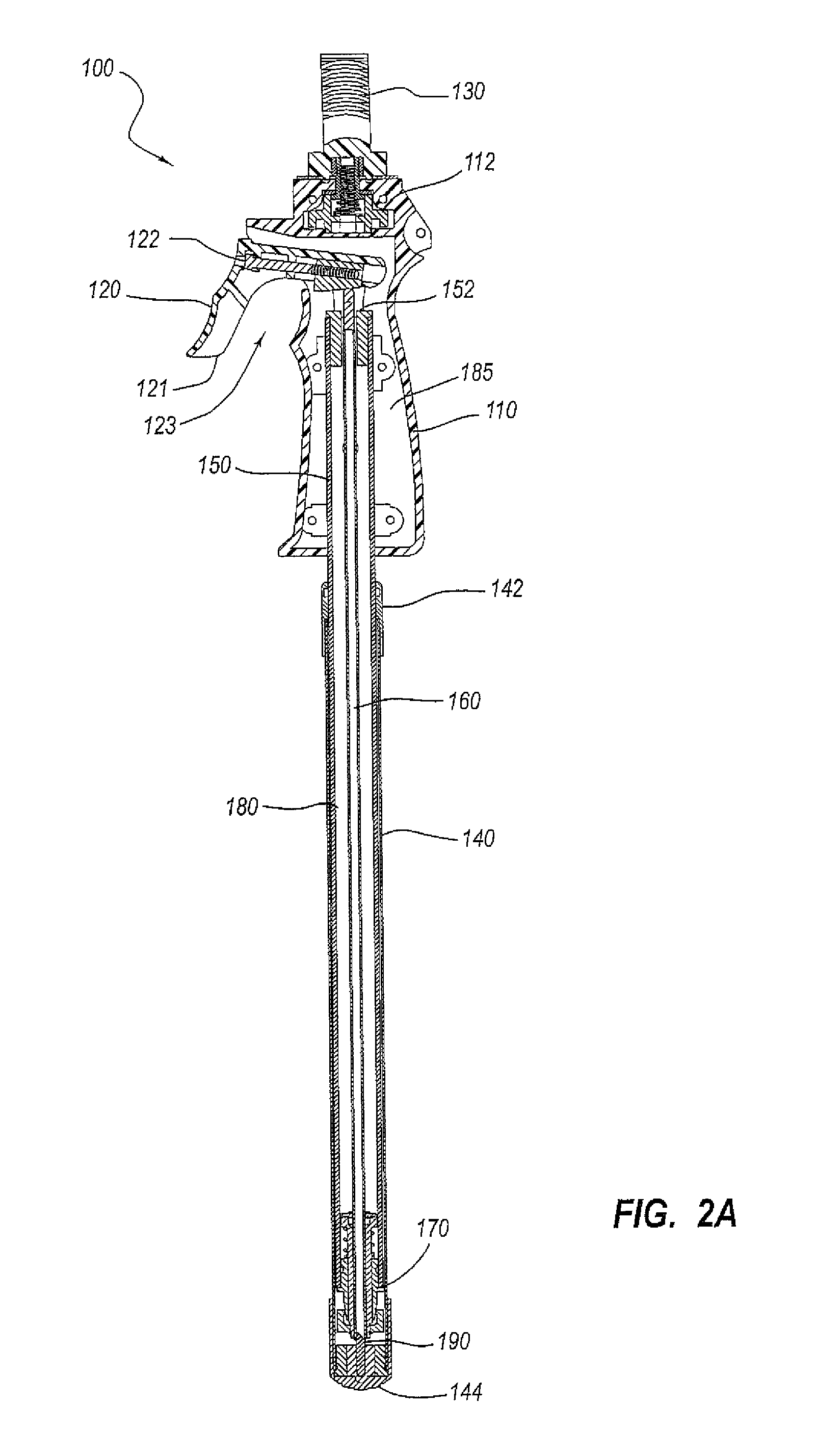
[0069]FIG. 1 is a perspective view of a telescoping support stand according to some embodiments. Telescoping support stand 100 may include an outer tube 140 and an inner tube 150, and inner tube 150 may be telescopically slidable within outer tube 140. Inner tube 150 may have a smaller diameter than outer tube 140, w...


PUM


Abstract

A telescoping support stand comprising a first tube partially defining a first enclosed area and a second tube partially defining a second enclosed area. A first end of the second tube may be telescopically slidable within the first tube. The telescoping support stand may also comprise a first locking mechanism attached to the second tube. The first locking mechanism may releasably secure the first tube to the second tube to prevent longitudinal movement of the first tube relative to the second tube. The telescoping support stand may also comprise a first air exchange aperture dimensioned to allow air to flow between the first and second enclosed areas. The telescoping support stand may further comprise a release mechanism and a release rod attached to the first locking mechanism. The release mechanism may comprise a displacement member adjacent to the release rod, the displacement member being configured to displace the release rod and release the first locking mechanism. A corresponding method of assembly is also disclosed.

Description

CROSS REFERENCE TO RELATED APPLICATION[0001]This application is a Continuation-in-Part of U.S. application Ser. No. 11 / 556,606, filed 3 Nov. 2006, the disclosure of which is incorporated, in its entirety, by this reference. Application Ser. No. 11 / 556,606, and likewise this application, claims the benefit of U.S. Provisional Application No. 60 / 771,751, filed 9 Feb. 2006, the disclosure of which is incorporated in its entirety by this reference.BACKGROUND[0002]Support stands, such as microphone stands and shooting stands, often include telescoping tubes that allow the height of the stands to be adjusted. These telescoping stands may have an inner tube, an outer tube, and a lock that keeps the inner tube from sliding relative to the outer tube. Such stands may be used in situations that require the stands to be rugged and capable of withstanding the elements. For example, hunter's shooting stands, microphone stands, telescope stands, and camera stands are often used outdoors. The comp...

Claims


Application Information

Patent Timeline
IPC IPC(8): F16M11/00
CPCF16M11/28F16M11/32F16B7/1409H04R1/08F16M2200/027Y10T403/32516Y10T403/32467
Inventor YOUNG, NATHAN E.FOSTER, ANTHONY A.
Owner BUSHNELL HLDG
Why Eureka
Try Eureka