
Atraumatic stent and method and apparatus for making the same

a stent and a technology of a stent and a stent body, applied in the field of atraumatic stents and methods, apparatus and systems for making the same, can solve the problems of unfavorable variation of radial expansion or compression forces, waste of material by trimming such excess wires, and stent wires of more expensive materials, so as to achieve the effect of improving quality control

Active Publication Date: 2012-04-10
BOSTON SCI SCIMED INC
View PDF25 Cites 45 Cited by
  • Summary
  • Abstract
  • Description
  • Claims
  • Application Information

AI Technical Summary

Benefits of technology

The present invention provides braiding methods, braiding mandrels, and braided stents that overcome the problems of previous braiding methods. The braided stents have a controlled braiding angle, including tapered portions, flared portions, and flanged portions. The braided stents also have variable diameter portions where the braiding angle is different. The braiding methods involve securing the filaments to the mandrel and using tensioned braiding carriers to braid the filaments. The resulting stents have improved mechanical properties and can be used for a variety of medical applications.

Problems solved by technology

Many stents, however, use metallic wires which may shift or move during braiding as a result of forces imparted on the wires during the braiding.
Variation in the braiding angle may result in undesirable variation of radial expansion or compression forces or deployment forces of the so formed stent.
The trimming of such excess wire needlessly wastes material.
More recently, however, stent wires of more expensive materials, such as nitinol or composite nitinol have been used.
The cost of the discarded material has become much more costly.

Method used


Image

  • Atraumatic stent and method and apparatus for making the same
  • Atraumatic stent and method and apparatus for making the same
  • Atraumatic stent and method and apparatus for making the same

Examples


embodiment 1

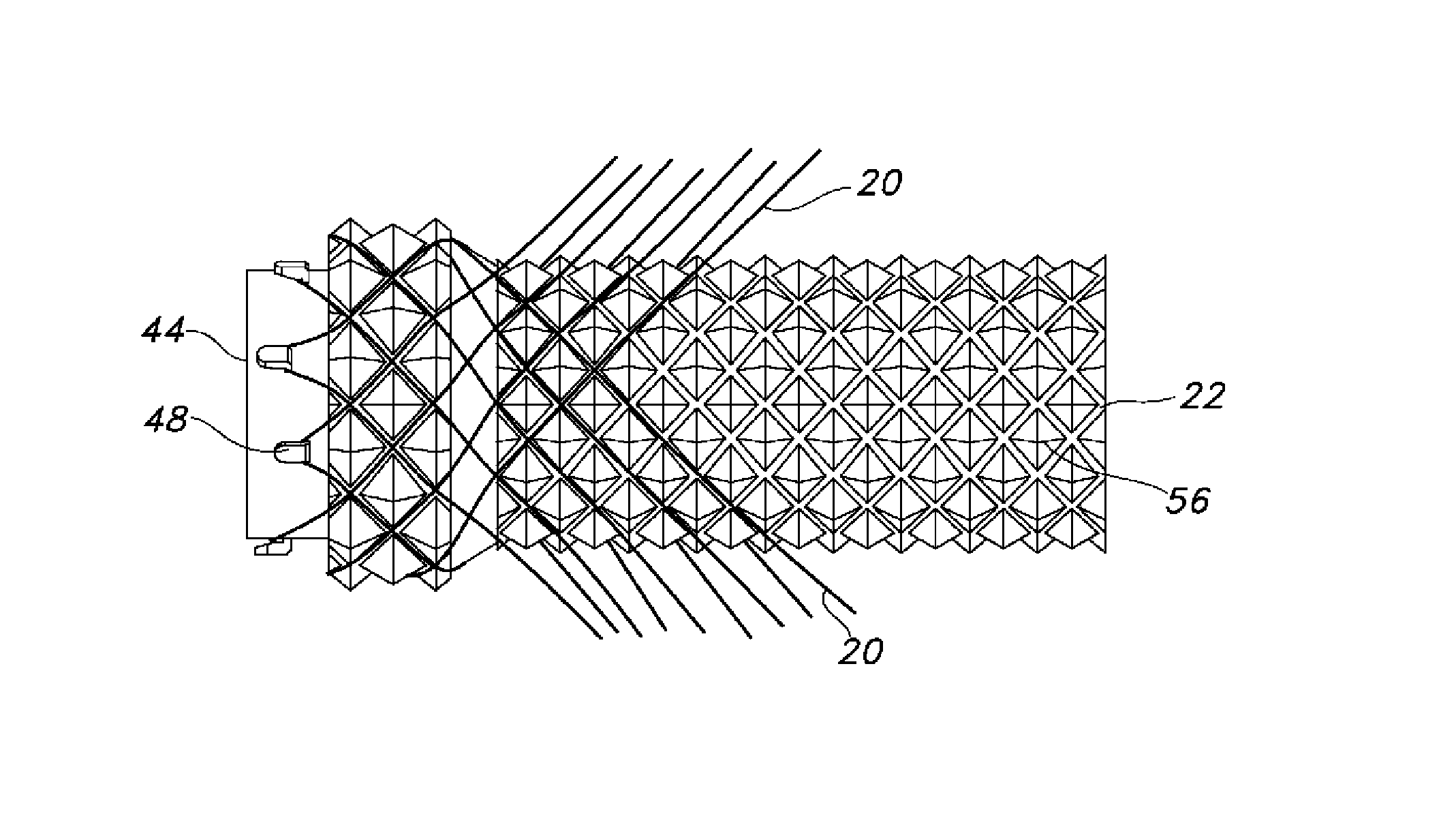
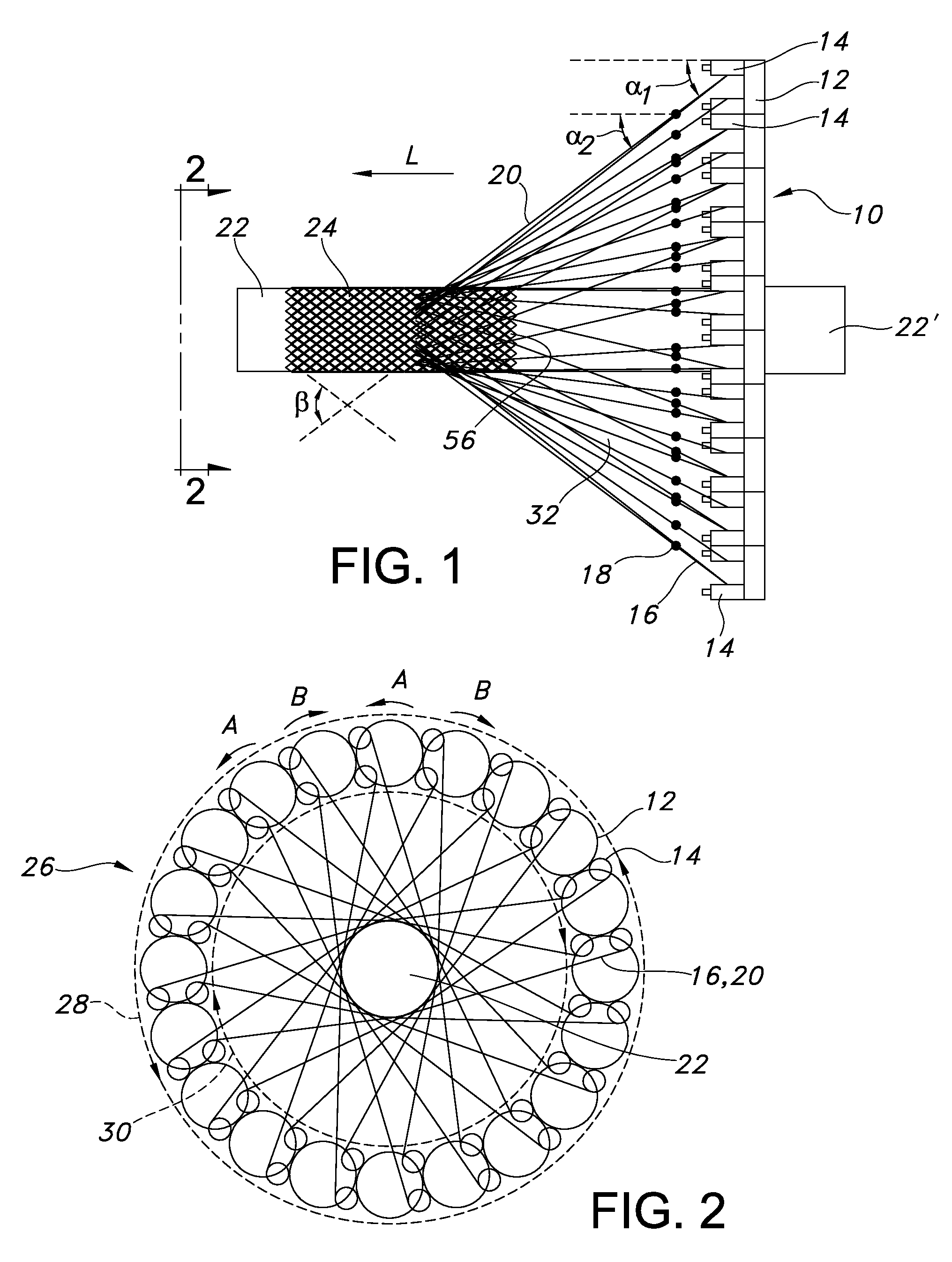
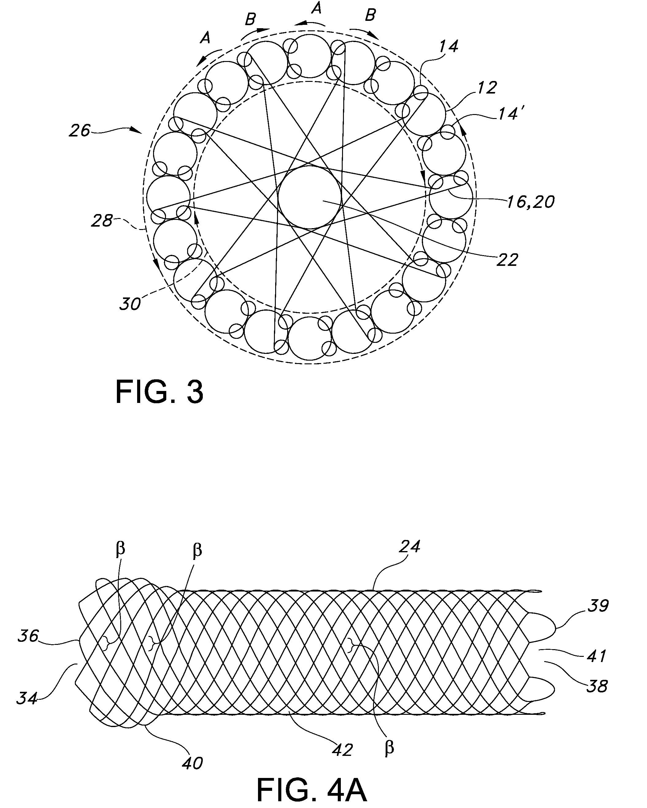
[0091]A method of braiding a stent comprising: (a) providing a number of elongate filaments, each of the filaments having opposed ends and an intermediate portion between the opposed ends; (b) providing a number of tensioned braiding carriers; (c) providing a braiding mandrel having opposed proximal and distal ends, the braiding mandrel comprising a number of circumferentially spaced-apart securement projections at the distal end of the braiding mandrel; (d) securably disposing the intermediate portion of one of the filaments to one of the securement projections; (e) securing one of the opposed ends of the one filament to one of the tensioned braiding carriers; (f) securing the other opposed end of the one filament to a different second tensioned braiding carrier; (g) repeating steps (d) through (f) until all of the intermediate portions of the filaments are securably disposed to different ones of the securement projections and until each end of the number of filaments are secured t...

embodiment 2

[0092]The method of embodiment 1, wherein step (h) includes moving the tensioned braiding carriers in a generally circular and serpentine motion about a circumferential plane of the mandrel.

embodiment 3

[0093]The method of embodiment 1, wherein the tensioned braiding carriers each comprise a retractable carrier filament and further wherein step (e) includes securing the one opposed end of the one filament to the retractable carrier filament of the one tensioned braiding carrier and step (f) includes securing the other opposed end of the one filament to the retractable carrier filament of the second tensioned braiding carrier.


PUM

PropertyMeasurementUnit
constant tension forceaaaaaaaaaa
tension forceaaaaaaaaaa
braiding angleaaaaaaaaaa

Abstract

A method of braiding a stent includes braiding a number of elongate filaments around a mandrel using tensioned braiding carriers without spooling the filaments to the tensioned braiding carriers to form a braided stent having atraumatic ends.

Description

CROSS-REFERENCE TO RELATED APPLICATIONS[0001]This application claims the benefit of U.S. Provisional Application No. 61 / 147,307, filed Jan. 26, 2009, the content of which is incorporated herein by reference.FIELD OF THE INVENTION[0002]The present invention is related to an atraumatic stent and methods, apparatus and systems for making the same. More particularly, the present invention is related to an atraumatic braided stent and braiding methods, braiding mandrels and braiding machines for making the same.BACKGROUND OF THE INVENTION[0003]Braided stents have typically been braided on a smooth mandrel. The ends of the braiding wires were typically gathered beyond an end of a braiding mandrel, and the wires where then secured, typically by tying or taping, to the mandrel end portion, after which braiding, either by hand or machine, commenced.[0004]The braiding angle was controlled by the angle at which the stent wires were disposed over the mandrel. Many stents, however, use metallic ...

Claims


Application Information

Patent Timeline
Patent Type & Authority Patents(United States)
IPC IPC(8): D04C1/00
CPCD04C1/06D04C3/48A61F2/90D04C3/14A61F2/82D10B2509/06A61F2250/0018A61F2230/0069A61F2240/00D02G1/02D02G3/28D02G3/448A61F2002/91516A61F2002/91525A61F2002/91508D04C1/02
Inventor LILBURN, STEVENORTON, PAUL K.ZUPKOFSKA, MICHAELBEDARD, LOUISHARDING, GLENN D.
Owner BOSTON SCI SCIMED INC
Learn More