Hydrolysis catalyst with larger duct cross-sections in the peripheral portion than in the central portion, and method for hydrolysis of a uric substance

a technology of hydrolysis catalyst and urea, which is applied in the direction of machine/engine, separation process, transportation and packaging, etc., can solve the problems of urea crystallization, blockage of exhaust line or other serious operational malfunctions, and urea crystallization, so as to achieve less expensive and simple

Inactive Publication Date: 2012-04-10
SCANIA CV AB
View PDF11 Cites 10 Cited by
  • Summary
  • Abstract
  • Description
  • Claims
  • Application Information

AI Technical Summary

Benefits of technology

[0009]The object of the present invention is to propose a significantly less expensive and simpler way than known solutions of preventing blockages or other operational malfunctions in an exhaust line containing a hydrolysis catalyst which are caused by crystallisation of injected urea or other uric substance.
[0011]Providing the catalyst element with ducts with different cross-sectional areas makes it possible for the exhaust flow to pass through the hydrolysis catalyst even if the exhaust flow contains urea which crystallises and consequently causes a greater or lesser degree of blockage in the ducts of smaller cross-sectional area. A blockage caused by crystallised urea in the ducts of smaller cross-sectional area will thus allow the exhaust flow to continue to pass through the ducts which are of larger cross-sectional area, and continued hydrolysis will also be facilitated by the fact that these ducts are lined with catalyst material. When the temperature of the exhaust gases has reached a sufficiently high level, the crystals will gradually be dissolved and the ducts of smaller cross-sectional area will again allow the exhaust gases to pass. Passage through the various portions of the catalyst element is thus regulated entirely automatically with no need for valves or the like.
[0012]According to an advantageous embodiment, the total cross-sectional area of the peripheral ducts is equal to the cross-sectional area of the outlet from the container which accommodates the hydrolysis catalyst. This means that even when the ducts with smaller cross-sectional areas are blocked, the exhaust flow will be able to pass without major counter-pressure.
[0013]According to an advantageous embodiment, the ducts with larger cross-sectional areas are turned in their axial extent, e.g., are spiralled along the axial direction. The result is a rotating exhaust flow which improves the mixing of the exhaust gases and ammonia which is converted in the hydrolysis catalyst, which improvement is advantageous for the functioning of the downstream SCR catalyst.

Problems solved by technology

A problem which arises in the injection of an aqueous solution of urea is that it readily crystallises if it encounters cold surfaces.
When the exhaust temperature rises, crystallised urea will certainly be dissolved but may, before that happens, cause blockages in the exhaust line or other serious operational malfunctions.
However, a problem which is particularly evident during low-load operation is that urea crystallises and obstructs the ducts in the hydrolysis catalyst.
The fact that this device comprises a number of additional components makes this a solution which is both bulky and expensive.
This unfortunately leads to the possibility that the pressure drop across a hydrolysis catalyst may be considerable.
This involves the disadvantage that the necessary additional components occupy space and that the costs increase.

Method used


Image

  • Hydrolysis catalyst with larger duct cross-sections in the peripheral portion than in the central portion, and method for hydrolysis of a uric substance
  • Hydrolysis catalyst with larger duct cross-sections in the peripheral portion than in the central portion, and method for hydrolysis of a uric substance

Examples


Embodiment Construction

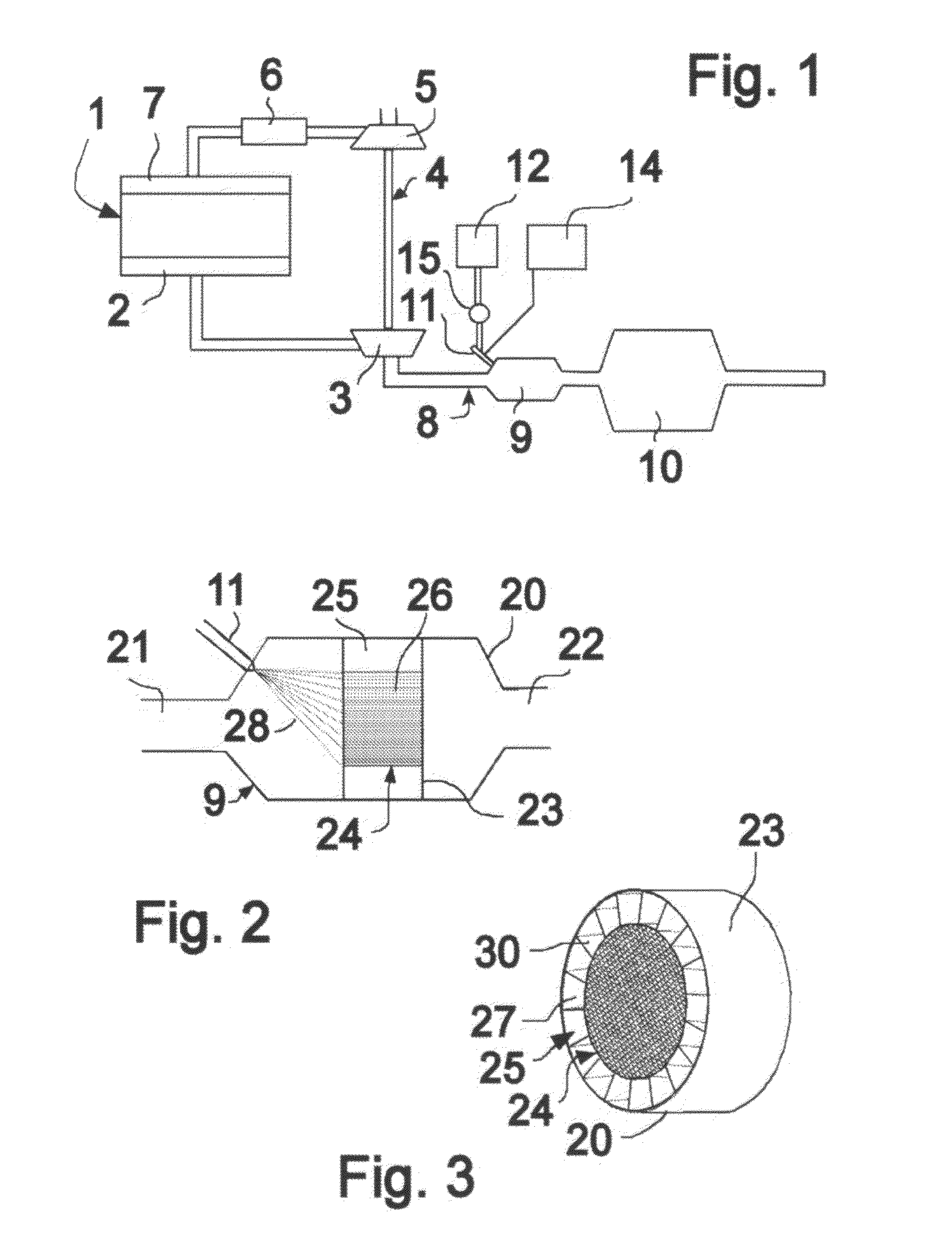
[0019]FIG. 1 depicts schematically an exhaust system for a multi-cylinder combustion engine 1, e.g. a diesel engine used to power a heavy vehicle. On the exhaust side of the engine 1, there is an exhaust manifold 2 from which the exhaust gases are first led to an exhaust turbine 3 which forms part of a turbocompressor 4 which also comprises a compressor 5 for supercharging of inlet air to the engine. The engine's inlet air is led from the compressor 5 to the engine 1 via a charge air cooler 6 and an inlet manifold 7. After the exhaust gases have passed through the turbine 3, they are led in an exhaust line 8 to a hydrolysis catalyst 9 and an SCR catalyst 10 before proceeding on in the exhaust line 8 to an undepicted silencer. A valve 11 is provided immediately upstream of the hydrolysis catalyst 9 for the injection of a suitable uric substance, which in this example takes the form of urea, into the hydrolysis catalyst 9 from a container 12 provided for the purpose. The valve 11 is c...


PUM

PropertyMeasurementUnit
cross-sectional areasaaaaaaaaaa
areasaaaaaaaaaa

Abstract

A hydrolysis catalyst forming part of an exhaust system for a combustion engine for catalytically converting a uric substance to ammonia which can be used in a downstream SCR catalyst. The hydrolysis catalyst includes an active catalyst element with a central portion and a surrounding peripheral portion, both of which are lined with the same catalyst material. To ensure that injected urea, or other uric substance, which can become crystallized, does not cause blockages in the catalyst, the cross-sectional areas of separate ducts in the peripheral portion are larger than the cross-sectional areas of the separate ducts in the central portion. A method for hydrolysis of a uric substance by use of the catalyst and directing flow through the ducts of the peripheral portion upon blockage of ducts in the central portion.

Description

CROSS REFERENCE TO RELATED APPLICATION[0001]This application claims priority from Swedish Application No. 0850019-1, filed on Sep. 23, 2008.BACKGROUND OF THE INVENTION[0002]The present invention relates to a hydrolysis catalyst intended for use in a combustion engine, particularly as part of an exhaust system, and more particularly to an improved construction of the hydrolysis catalyst.[0003]A known practice in combustion engines is for the exhaust gases to be treated by various post-treatment systems with the object of reducing the proportion of harmful constituents in the exhaust gases. A known way of reducing the proportion of nitrogen oxides is to use an SCR catalyst in which ammonia being mixed with the exhaust gases makes it possible to reduce the nitrogen oxides to nitrogen gas and water. To avoid injecting pure ammonia into the exhaust gases, what is used instead is a more easily handled substance, usually a uric substance, such as an aqueous solution of urea, which when inj...

Claims


Application Information

Patent Timeline
Patent Type & Authority Patents(United States)
IPC IPC(8): B01D50/00F01N3/00F01N3/10
CPCB01F3/04049F01N3/2066F01N13/0097F01N3/2892B01D2251/2067B01D2257/404B01D2258/01F01N2240/20F01N2240/40F01N2610/02Y02T10/24Y02T10/12B01F23/2132F01N3/2803F01N2570/14F01N3/206
Inventor KLINGBERG, THOMAS
Owner SCANIA CV AB
Why Eureka
Try Eureka