
Mobile communications systems and methods relating to polarization-agile antennas

a mobile communication system and antenna technology, applied in the field of wireless communication, can solve the problems of achieving only a few decibels of improvement, unable to achieve more than a small fraction of the theoretically available performance, and requiring a lot of effort in developing complex signal processing algorithms

Inactive Publication Date: 2012-04-10
L 3 COMM CORP +1
View PDF17 Cites 5 Cited by
  • Summary
  • Abstract
  • Description
  • Claims
  • Application Information

AI Technical Summary

Benefits of technology

"The invention is about improving wireless communication systems by adapting to the way signals are transmitted through the air. This is done by using a special antenna that can change the way signals are polarized, which can affect their transmission. By selecting the best polarization mode for the changing channel, the system can improve performance. The invention also includes a method for predicting how well the system will perform based on the characteristics of the channel. Overall, the invention makes wireless communication more efficient and reliable."

Problems solved by technology

While theoretical performance limits can be calculated for many wireless communications scenarios, often system implementations fail to achieve more than a small fraction of the theoretically available performance.
Much effort has been exerted in developing complex signal processing algorithms which, in some cases, provide only a few decibel of improvement.
Unfortunately, complex signal processing is generally required in order to obtain the increased throughput.
The size and cost impact of adding antennas and cost of increased signal processing has slowed the adoption of MIMO technology.
The impact of additional antennas and processing has caused some to view MIMO as impractical for mobile communications systems.

Method used


Image

  • Mobile communications systems and methods relating to polarization-agile antennas
  • Mobile communications systems and methods relating to polarization-agile antennas
  • Mobile communications systems and methods relating to polarization-agile antennas

Examples


Embodiment Construction

)

[0022]Additional features and advantages of the invention will be apparent from the detailed description which follows, taken in conjunction with the accompanying drawings, which together illustrate, by way of example, features of the invention. In describing embodiments of the present invention, the following terminology will be used.

[0023]The singular forms “a,”“an,” and “the” include plural referents unless the context clearly dictates otherwise. Thus, for example, reference to “an antenna” includes reference to one or more of such antennas.

[0024]As used herein, a plurality of items, structural elements, compositional elements, and / or materials may be presented in a common list for convenience. However, these lists should be construed as though each member of the list is individually identified as a separate and unique member. Thus, no individual member of such list should be construed as a de facto equivalent of any other member of the same list solely based on their presentati...


PUM

PropertyMeasurementUnit
polarization anglesaaaaaaaaaa

Abstract

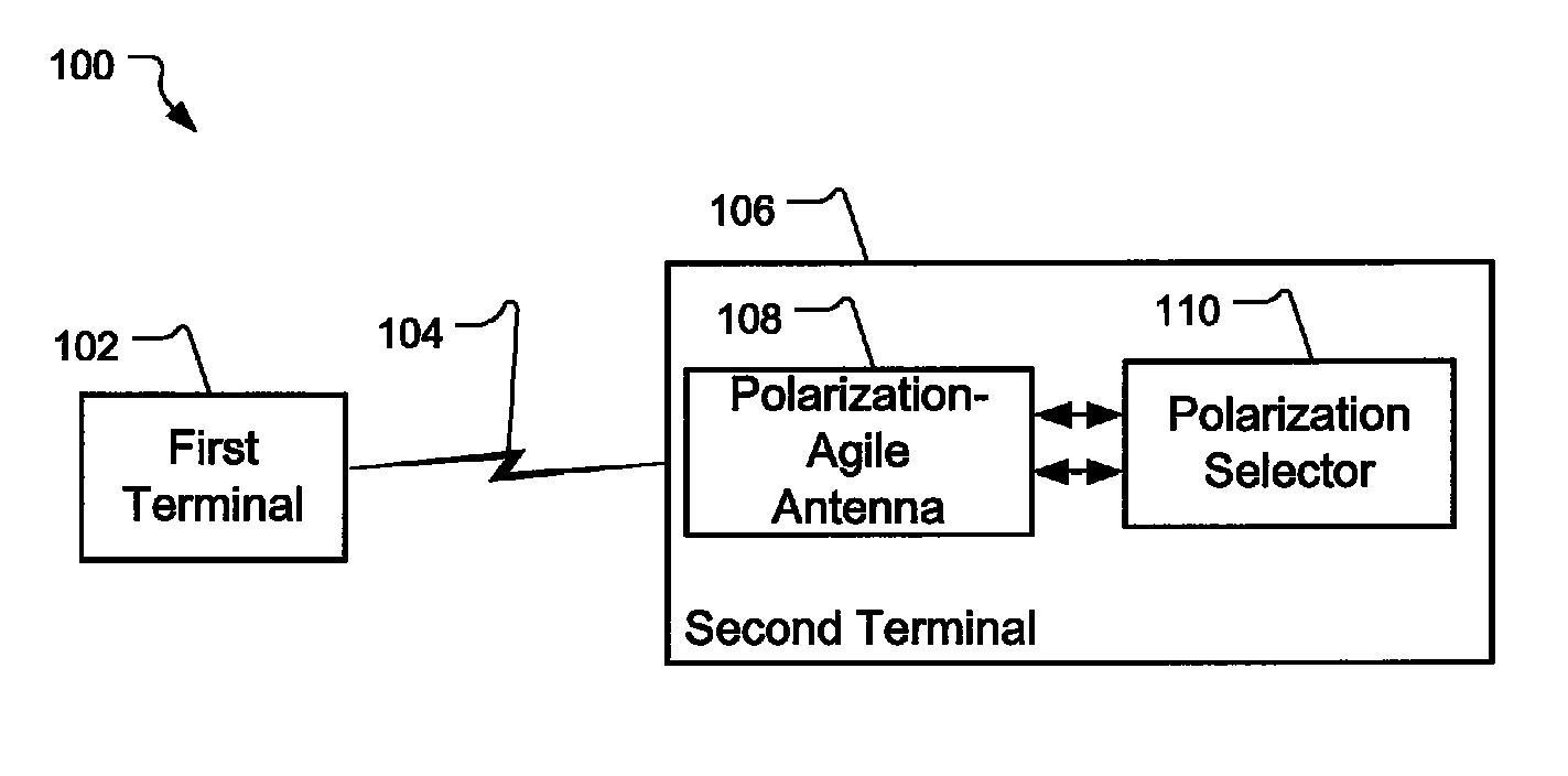
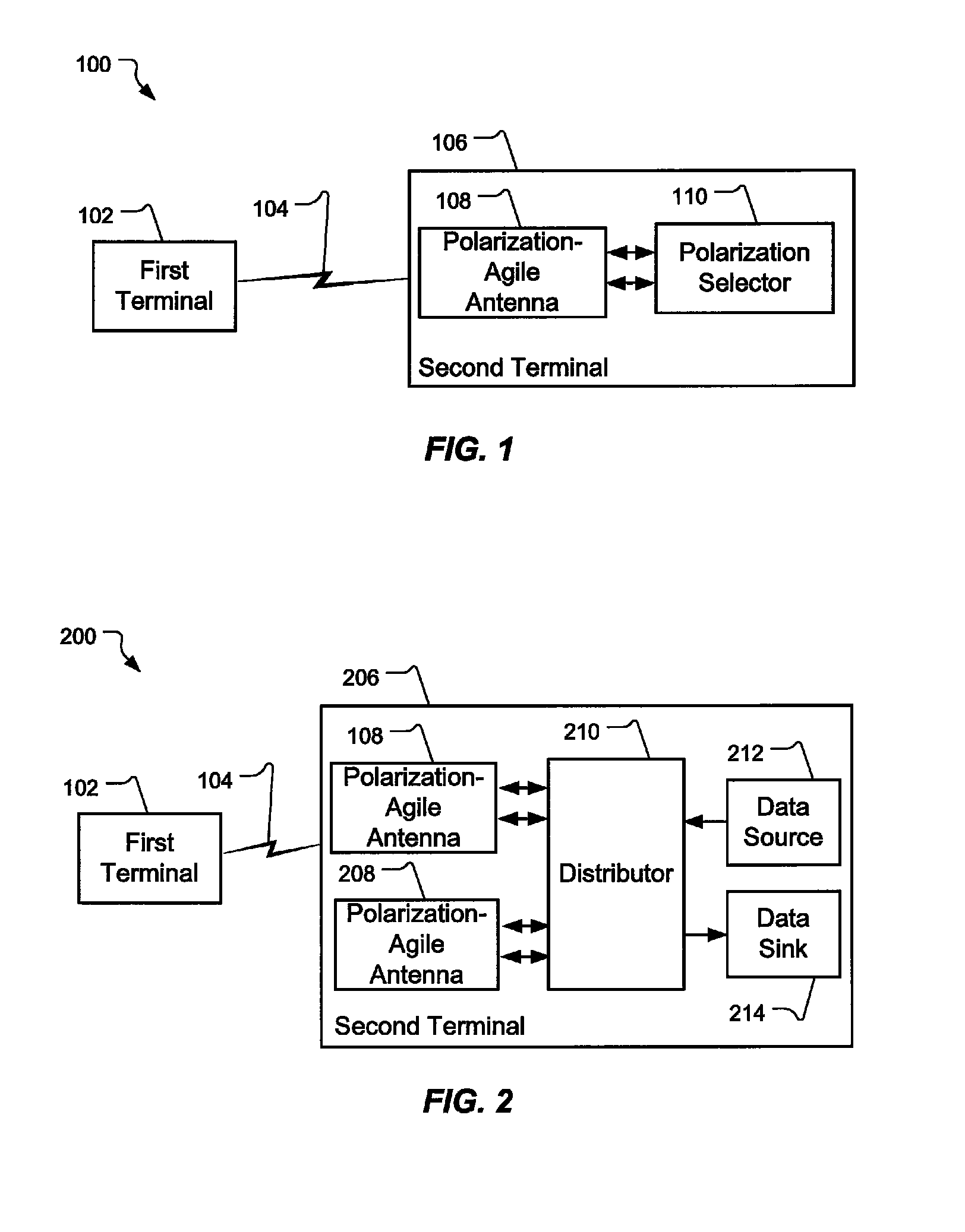
A wireless communication system can include polarization agile antennas to enable adaptation to the polarization characteristics of a changing propagation channel. In one embodiment, a mobile terminal can include one or more polarization-agile antennas, and can select polarization orientations that are preferentially propagated through the changing propagation channel. In another embodiment, a mobile terminal having two polarization-agile antennas can provide spatial diversity, polarization diversity, or combinations of both. Multiple-input multiple-output (MIMO) systems can include polarization-agile antennas to allow for switching between spatial and polarization diversity, combined spatial and polarization diversity, and various Eigen channel decompositions using spatial, polarization, and combined spatial and polarization dimensions. An extended polar normalization provides enhanced fidelity for methods of communications system modeling.

Description

[0001]This application claims the benefit of U.S. Provisional patent application Ser. No. 60 / 875,699 filed Dec. 18, 2006, entitled “Mobile Communications Systems and Methods Relating to Polarization-Agile Antennas,” which is hereby incorporated by reference.GOVERNMENT RIGHTS[0002]This invention was made with government support under Grant #ECS0524720 awarded by the National Science Foundation. The government has certain rights to this invention.BACKGROUND[0003]1. Field of the Invention[0004]The present invention relates generally to wireless communication. More particularly the present invention relates to wireless communication using radio frequency signals.[0005]2. Related Art[0006]Wireless communications systems, and in particular multiple-input multiple-output (MIMO) systems, have achieved remarkable capacity gains in the last decade. While theoretical performance limits can be calculated for many wireless communications scenarios, often system implementations fail to achieve mo...

Claims


Application Information

Patent Timeline
Patent Type & Authority Patents(United States)
IPC IPC(8): H01Q1/38
CPCH04B7/10H04B7/0689Y10T29/49018H04B7/0871
Inventor LANDON, DAVID GLENFURSE, CYNTHIA MAHONEY
Owner L 3 COMM CORP
Learn More