Foot pad structure

a foot pad and structure technology, applied in the direction of machine supports, instruments, casings/cabinets/drawers of electric apparatus, etc., can solve the problems of affecting the structural strength, the electronic system positioned on the supporting plane is actually in an unstable state, and the full-assembly electronic system, etc., to achieve stably positioned and high compressive deformation

Active Publication Date: 2012-04-10
ACER INC
View PDF2 Cites 11 Cited by
  • Summary
  • Abstract
  • Description
  • Claims
  • Application Information

AI Technical Summary

Benefits of technology

[0005]A primary object of the present invention is to provide a foot pad structure for mounting to a bottom of an electronic system, such as a notebook computer, so that the electronic system would not wobble when a user operates thereon even if the bottom of the electronic system is in a non-level condition due to manufacturing or assembling errors of the electronic system or positioning of the electronic system on a non-planar surface.
[0008]A secondary object of the present invention is to provide an electronic system having a foot pad structure mounted to a bottom of the electronic system, such as a notebook computer, so that the electronic system would not wobble when a user operates thereon even if the bottom of the electronic system is in a non-level condition due to manufacturing or assembling errors of the electronic system or positioning of the electronic system on a non-planar surface.
[0010]With the air chamber and the through holes provided on the foot pad structure of the present invention, when the elastic pad member is compressed by an external force, part of the air stored in the air chamber can be expelled via the communicating through holes into external environment, allowing the elastic pad member to have high compressive deformation. That is, the foot pad structure of the present invention is able to modify any non-levelness of an electronic system caused by unevenly distributed weight thereof, so that the electronic system can always be stably positioned on a work plane without wobbling when a user operates, such as types on the electronic system.

Problems solved by technology

It is frequently found that a fully assembled electronic system, such as a notebook computer, fails to have all the foot pads thereof in contact with a supporting plane, such as a disk top.
With one of the foot pads thereof suspended in the air, the electronic system positioned on the supporting plane is actually in an unstable state.
This condition might be caused by errors in manufacturing a bottom cover of the electronic system, such as errors in thermal injection molding or thermal die-casting, which would adversely affect the structural strength and the levelness of the bottom cover to result in deformation thereof.
Further, errors in assembling and unevenly distributed weight on the bottom cover would also render the electronic system in a non-level state.
Particularly, the currently very popular small notebook computers, netbook computers, mobile Internet devices, and ultra-mobile personal computers, due to their small size, tend to wobble easily when they are positioned on a work surface in a non-level condition, preventing a user from comfortably operating or keying on them.

Method used


Image

  • Foot pad structure
  • Foot pad structure
  • Foot pad structure

Examples


Embodiment Construction

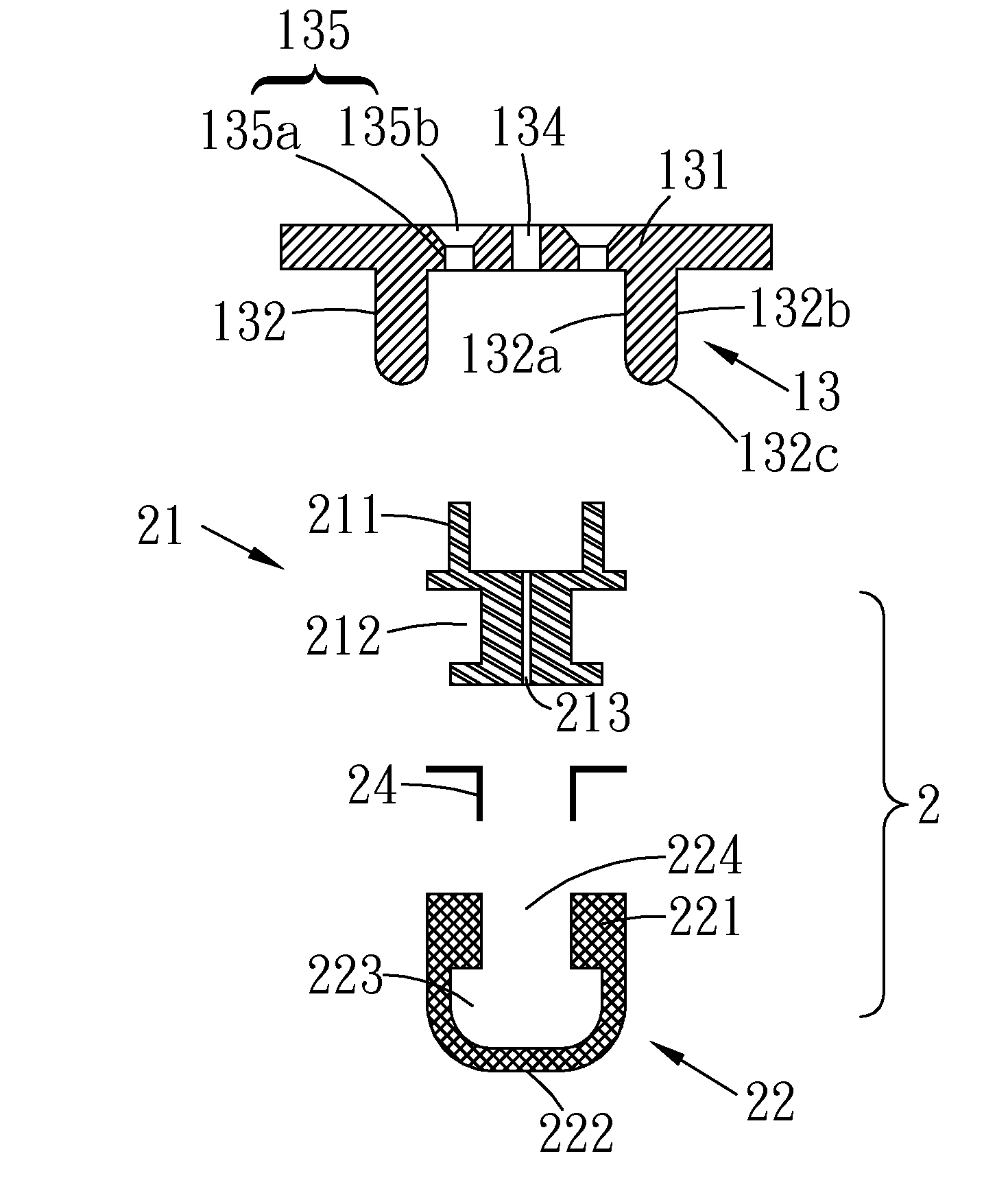
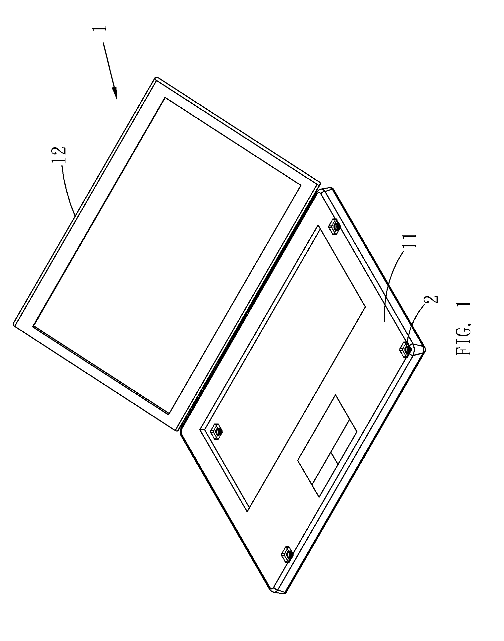
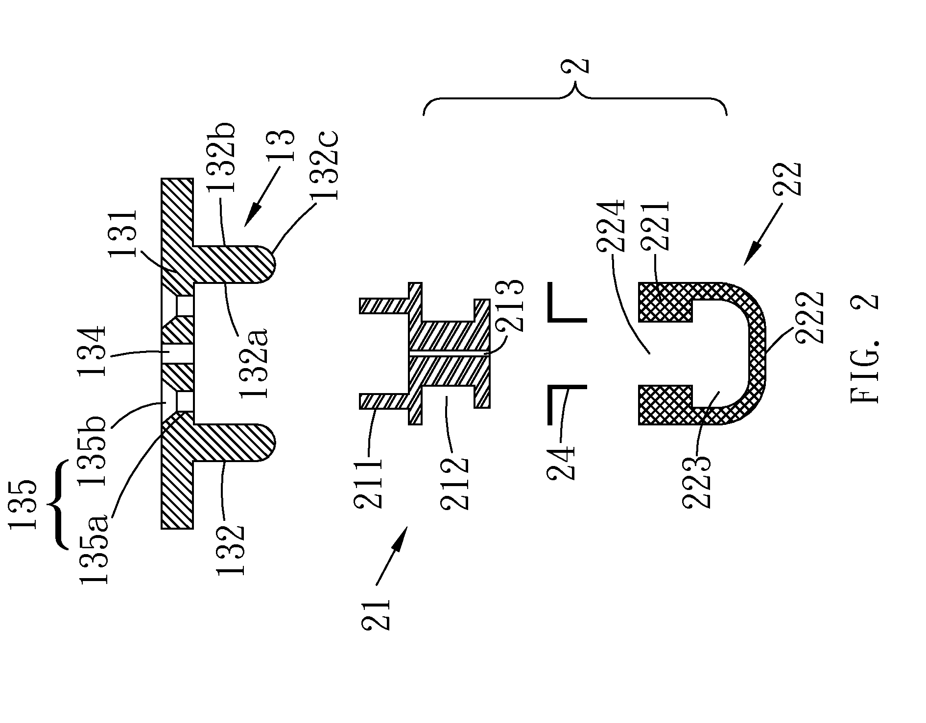
[0025]Please refer to FIG. 1 that generally shows the foot pad structure according to the present invention can be externally mounted to different locations at a bottom of an electronic system; and to FIG. 2 that is an exploded sectional view showing a foot pad structure 2 according to a first embodiment of the present invention. As shown, the foot pad structure 2 is assembled from a retaining member 21 and an elastic pad member 22 for externally mounting to a bottom of an electronic system 1. In the illustrated first embodiment, the electronic system 1 can be a notebook computer, a netbook computer, a mobile Internet device, or an ultra-mobile personal computer (UMPC). The electronic system 1 has a housing, and the housing comprises a base portion 11, a pivotal cover portion 12 turnable relative to the base portion 11. The electronic system 1 further comprises a plurality of receiving portions 13, to each of which one foot pad structure 2 of the present invention is correspondingly...


PUM


Abstract

A foot pad structure includes a retaining member and an elastic pad member. The retaining member is mounted to a receiving portion formed on a bottom of an electronic system and has a second through hole communicable with a first through hole formed in the receiving portion to thereby communicate with external environment via the first through hole. The elastic pad member internally defines an air chamber that communicates with the second through hole. The elastic pad member is retained between the retaining member and the receiving portion with a lower part thereof downward protruded beyond the receiving portion. When the elastic pad member is compressed, air in the air chamber is expelled into the external environment via the first and second through holes, allowing the elastic pad member to deform for the electronic system to stably position on a work surface without wobbling when the electronic system is operated.

Description

FIELD OF THE INVENTION[0001]The present invention relates to a foot pad structure, and more particularly to a foot pad structure for mounting to a bottom of an electronic system.BACKGROUND OF THE INVENTION[0002]Many electronic systems have stabilizing or wear-resisting foot pads mounted to a bottom thereof. In the prior art, such foot pads are usually made of a rubber or plastic material and are bonded to the bottom of the electronic systems by heat melting the rubber or plastic foot pads.[0003]It is frequently found that a fully assembled electronic system, such as a notebook computer, fails to have all the foot pads thereof in contact with a supporting plane, such as a disk top. With one of the foot pads thereof suspended in the air, the electronic system positioned on the supporting plane is actually in an unstable state. This condition might be caused by errors in manufacturing a bottom cover of the electronic system, such as errors in thermal injection molding or thermal die-ca...

Claims


Application Information

Patent Timeline
Patent Type & Authority Patents(United States)
IPC IPC(8): G06F1/16
CPCF16M13/00G06F1/1656H05K5/0234F16M2200/08
Inventor CHEN, SHUN-BIN
Owner ACER INC
Why Eureka
Try Eureka