Fan, airfoil and vehicle propulsion systems

a technology of airfoil and propulsion system, which is applied in the direction of machines/engines, stators, liquid fuel engines, etc., can solve the problems of misunderstanding of the way an airfoil produces lift, historically limited development and success of ground-effect type vehicles, and may have had common problems associated with traditional aircraft raised, etc., to achieve increased thrust and lift, low maintenance, and increased speed and maneuverability

Inactive Publication Date: 2012-04-17
KOLACNY GORDON S +1
View PDF7 Cites 10 Cited by
  • Summary
  • Abstract
  • Description
  • Claims
  • Application Information

AI Technical Summary

Benefits of technology

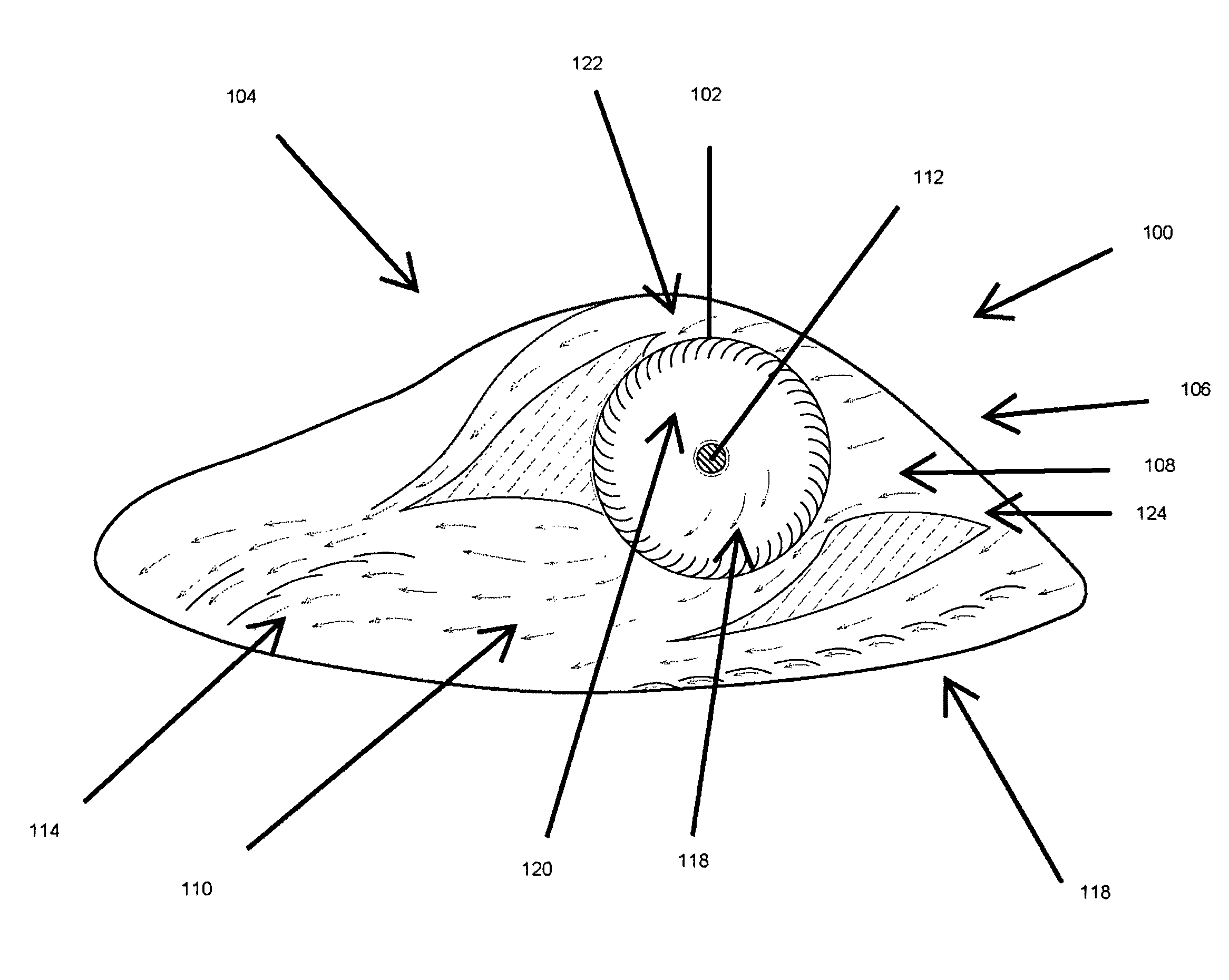
[0021]The invention is scalable to accommodate preferred lift and thrust. In some embodiments, the invention has a scalable cross flow fan, as well as other scalable features, that produce lift and thrust corresponding to determined lift and thrust requirements. Whereas some traditional systems may be understood as one-dimensional in flight control, limiting its application and generally producing only thrust, and lift only after significant thrust and linear horizontal or vertical movement is obtained, the present invention, incorporating a modified cross flow fan configuration in preferred embodiments, provides a highly efficient, low-drag design having a high-lift multi-airfoil technology.
[0042]Embodiments the present invention provide for a combination advantages, some of which may be described previously and further described as: instant take-off and landing; hover capabilities for fixed wing aircraft; functional jet capabilities such as in linear RAM jet capabilities with no forward movement requirement; three dimensional flight control and no or slow flight speeds; high speed laminar air flows around lifting and control surfaces even at a stop or no or low flight speed; laminar air flow offering boundary layer control; rotating manifold features offering greater lift when needed; an angle of attack of the system may be considered fixed relative to the manifold and multi-airfoils that addressing stalling factors; no or minimized adverse torque reaction; a torque reaction that contributing to lift; controlled flight in loss of power or stall situations; sufficient lift with less wing surface; thin, high aspect ratio airfoils reduce drag, weight, and storage space; low thermal signature for stealth applications; a design providing lower costs in simple maintenance configurations.

Problems solved by technology

Ground-effects type vehicles, such as amphibious air driven technologies and hover craft, as well as vertical take-off and landing vehicles, may have had historically limited development and success due to the previous complexity of traditional aeronautical theory and its potential inaccuracies.
It is with the traditional design of airfoils for aircraft and how the airfoil is traditionally incorporated for flight that commonly known problems associated with traditional aircraft are raised.
One such identified problem is the common misunderstanding of how an airfoil produces lift.
Furthermore, induced drag may be a factor wherein rearward thrust of circulation may be greater than forward thrust.
In respect to this traditional theory, losses in lift may be due in part to upward circulation around the wing ends.
Some studies have found, however, that the airfoil commonly referred to as an accelerating or acceleration airfoil outperforms conventional airfoils by an increase in flow velocities and pressure differentials for lift.
In some circumstances, the additional complexity was to design an aircraft that could generate on its own enough initial lift to allow the aircraft to take off at a non-moving initial position and even to provide some aspects of hovering while in flight or from the take off.
The Harrier Jet technology is relatively expensive and may be difficult to maintain, while another primary deterrent is the apparent lack of precise control desirable for certain applications, such as preferred three-dimensional flight control and low or even no flight speed control.
In one example, a potential downside is the lack of provision for a stall or loss of power in which the pilot would have very little option in attempting to land the plane without power to provide thrust and lift for a safe landing.
Furthermore, the Harrier design may not take advantage of more preferable airfoil designs and configurations that would result in greater lift and thrust, in take off, flight, and landing, particularly as a winged and jet engine driven aircraft.
Additionally the Harrier Jet design incorporates technology and resultant thrust effects that may be undesirable with respect to the location of takeoff and landing of the jet, such as over surfaces that are detrimentally affected by the weight of the aircraft generally and the downward thrust of secondary jet engines to achieve lift.
The technology is relatively expensive, while another primary deterrent is the apparent lack of precise control desirable for certain applications, such as preferred three-dimensional flight control and low or even no flight speed control.
The problems and deterrents may have been reflected in the number of setbacks the military and developers had in producing serviceable aircraft.
Again, a further potential downside is the lack of provision for a stall or loss of power in which the pilot would have very little options in attempting to land the plane without power to provide thrust and lift for a safe landing.
Furthermore, the Osprey may not take advantage of more preferable airfoil designs and configurations that would result in greater lift and thrust, both in take off, in flight, and in landing, particularly as a winged and propeller driven aircraft.
Craft that have actually been produced in real world application are designs commonly referred to as hover craft and typically lack preferred control over thrust and lift in order to achieve propulsion, much less precise control desirable for certain applications such as preferred three-dimensional flight control and low or even no flight speed control.
Some of these designs may not address control over production of thrust in combination with lift in order to propel the vehicle forward or to lift the vehicle from ground surface.
While many of these drawbacks and inadequacies in the prior art are known and documented, no heretofore developed technology has adequately addressed these needs, and the traditional technologies described above do not bridge the gap or fully achieve preferred control over lift and thrust for propulsion, or to do so for standing take off, to hover, and in takeoff, flight, landing and loss of power scenarios for aircraft.
Heretofore generating a controlled combination of thrust and lift for precise and controlled flight and landing in the absence of power supplied to the propulsion system has not been adequately addressed or achieved in traditional designs.
Furthermore, it may have even been thought as a recognized drawback in aeronautic and ground-effect systems to incorporate the provision for controlled thrust and lift to accommodate not only lift but as also the source for thrust in forward travel or flight.
It may have also been heretofore thought that airfoil design could not be achieved that would provide the necessary lift for real world applications of vehicle dimensions and weight, particularly for any airfoil design beyond traditional single wing aircraft.
In addition to all of the deficiencies previously described, the prior art may suffer from one or more of the following deficiencies.
The prior art may require further and additional thrust and lifting systems and separate and additional power generation for the propulsion system to achieve a desired result, such as in the take-off and flight of traditional aircraft or in the lack of provision for propulsion in the event of power loss during flight.
The prior art may not even provide for the combination of control of thrust and lift, such as preferred three-dimensional flight control and low or even no flight speed control, and for the full propulsion of a vehicle such as an aircraft or ground-effects vehicle.
The prior art may even lack the preferred understanding of airfoil design and implementation into a propulsion system, potentially only directed to lift by air flow.

Method used


Image

  • Fan, airfoil and vehicle propulsion systems
  • Fan, airfoil and vehicle propulsion systems
  • Fan, airfoil and vehicle propulsion systems

Examples


Embodiment Construction

[0065]The present invention is described in preferred embodiments that address one or more inadequacies of the prior art. Accordingly, embodiments of the invention are shown and described in the Figures, summary of the invention, written description, and claims and throughout the disclosure of this application, as one or more apparatus, assemblies, processes, and methods.

[0066]The present invention is herein described as embodiments of vehicles and methods of propulsion, wherein vehicles may be any transport system or technology, such as, but not limited to, vehicles generally, and aeronautic applications and ground-effects type vehicle design and operation, such as traditional private and commercial aircraft, as well as military and aerospace applications for aircraft, shuttles, and other vehicles, as well as primarily surface-based vehicles such as amphibious vehicles and hovercraft. The term vehicle may reference aircraft, space craft, land craft, water craft, hover craft, and ot...


PUM


Abstract

Vehicle propulsion systems and methods of propulsion are disclosed, as well as embodiments of fans and airfoils, technology that in some applications of the invention can provide both lift and thrust, and propulsion via cross flow fan, manifold and a plurality of airfoils. In some embodiments the invention is directed to the production of lift and thrust, and propulsion generally, based from air produced by a cross flow fan in accordance with the invention disclosed herein. In still further embodiments, lift and thrust may yet be generated from air produced from the cross flow fan even when unpowered, such as in a loss of power or in a stall condition. Applications of the invention apply broadly to propulsion systems, generally; however, some preferred embodiments have particular application for vehicles characterized or used in application such as traditional private and commercial aircraft, ground effects vehicles, military applications, amphibious applications, aerospace, aeronautical, and non-traditional vehicles such as experimental air planes, space craft, hover craft, and the like. The invention in some embodiments comprises technologies addressing preferred air flow, lift, and thrust and the reduction of drag and circulation losses. The invention may be further applicable for incorporation in aircraft and other vehicles wherein the ability to maximize initial vertical lift and takeoff is important, such as in instant take-off and landing, as well as the abilities to hover, to control the flight and landing of aircraft, and control in power-loss scenarios, addressing the prevention of stalls and allowing for controlled descents under continued propulsion. In some embodiments, the invention is further applicable for aircraft, shuttles and other vehicles as a ram jet engine system as a further alternative propulsion technology, having no requirement for forward movement for propulsion upon take-off.

Description

[0001]The invention is directed to air flow technologies in tangential and cross flow fan systems, as well as to airfoil technologies for aeronautic and ground-effects applications, among others. The invention in some embodiments comprises technologies addressing preferred air flow, lift, and thrust, as well as propulsion generally, and the reduction of drag and circulation losses. The invention is applicable to aeronautic applications and ground-effects type vehicle design and operation, such as traditional private and commercial aircraft, as well as military and aerospace applications for aircraft, shuttles, and other vehicles, as well as primarily surface-based vehicles such as amphibious vehicles and hovercraft. The invention is further applicable for incorporation in aircraft and other vehicles wherein the ability to maximize initial vertical lift and takeoff is important, such as in instant take-off and landing, as well as the abilities to hover, to control the flight and land...

Claims


Application Information

Patent Timeline
Patent Type & Authority Patents(United States)
IPC IPC(8): F03B1/00F03B3/04
CPCF04D17/04
Inventor KOLACNY, GORDON S.KOLACNY, BRUCE A.
Owner KOLACNY GORDON S
Why Eureka
Try Eureka