Contact for electrical connector

a technology of electrical connectors and contacts, applied in the field of contact, can solve problems such as the difficulty of forming the first hooks

Active Publication Date: 2012-04-17
HON HAI PRECISION IND CO LTD
View PDF7 Cites 14 Cited by
  • Summary
  • Abstract
  • Description
  • Claims
  • Application Information

AI Technical Summary

Benefits of technology

[0007]Accordingly, an object of the present invention is to provide a contact comprising a first contact pin and a second contact pin having simple configurations and being capable to establish a reliable engagement therebetween.
[0009]It is easy to form a pair of ear portions on the first contact pin. The engagement between the ear portions of the first contact pin and the resilient beams of the second contact pin is reliable.

Problems solved by technology

It is complicated to form the first hooks on the first contact pin and the second hooks on the second contact pin.

Method used


Image

  • Contact for electrical connector
  • Contact for electrical connector
  • Contact for electrical connector

Examples


Embodiment Construction

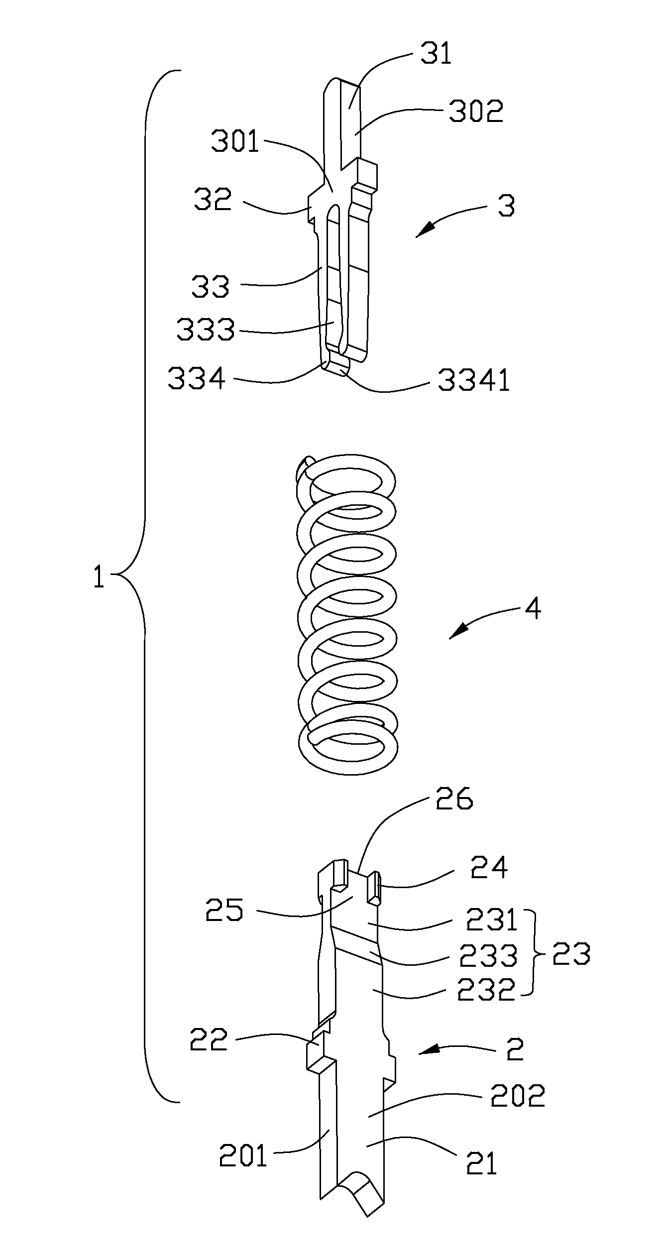
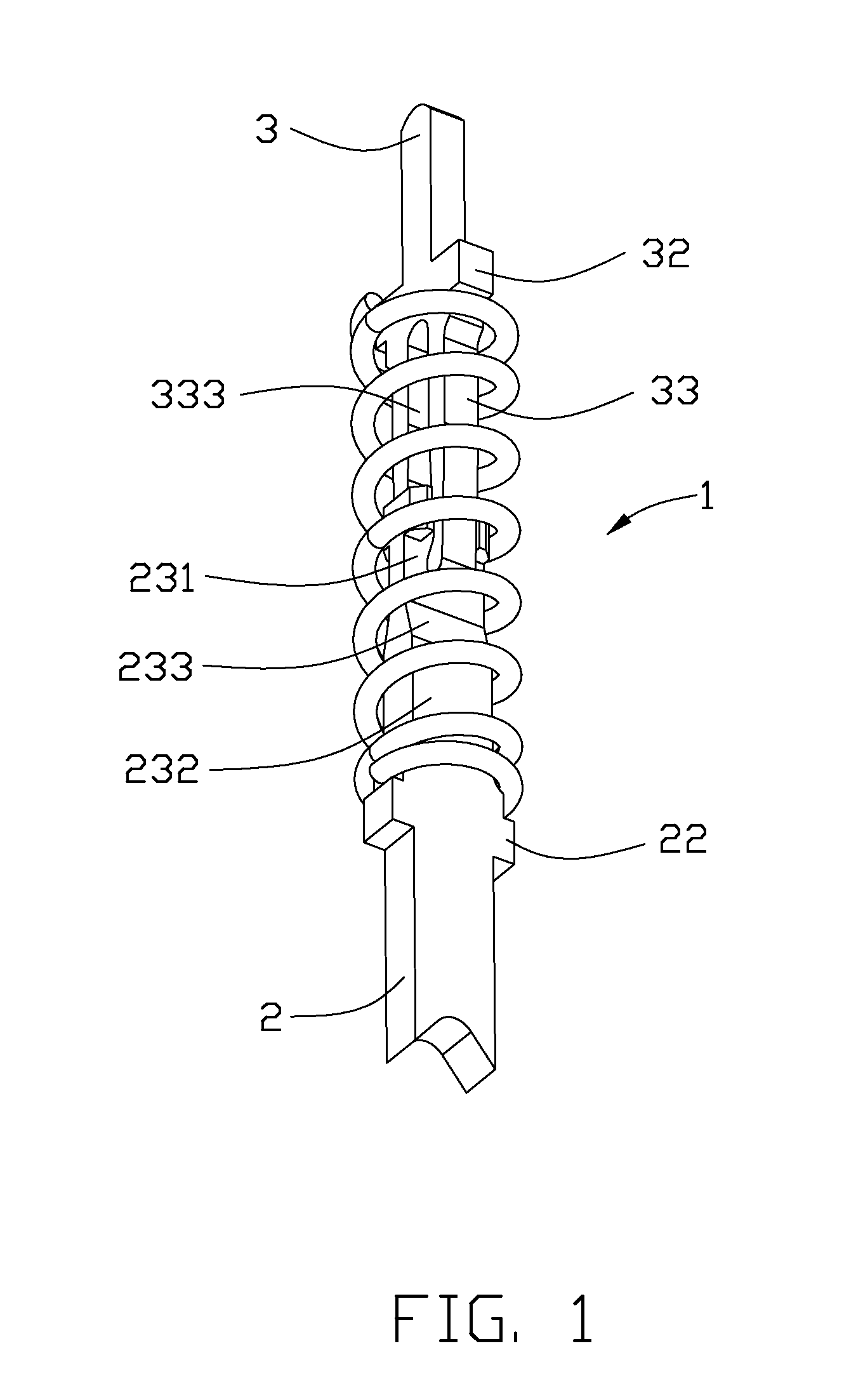
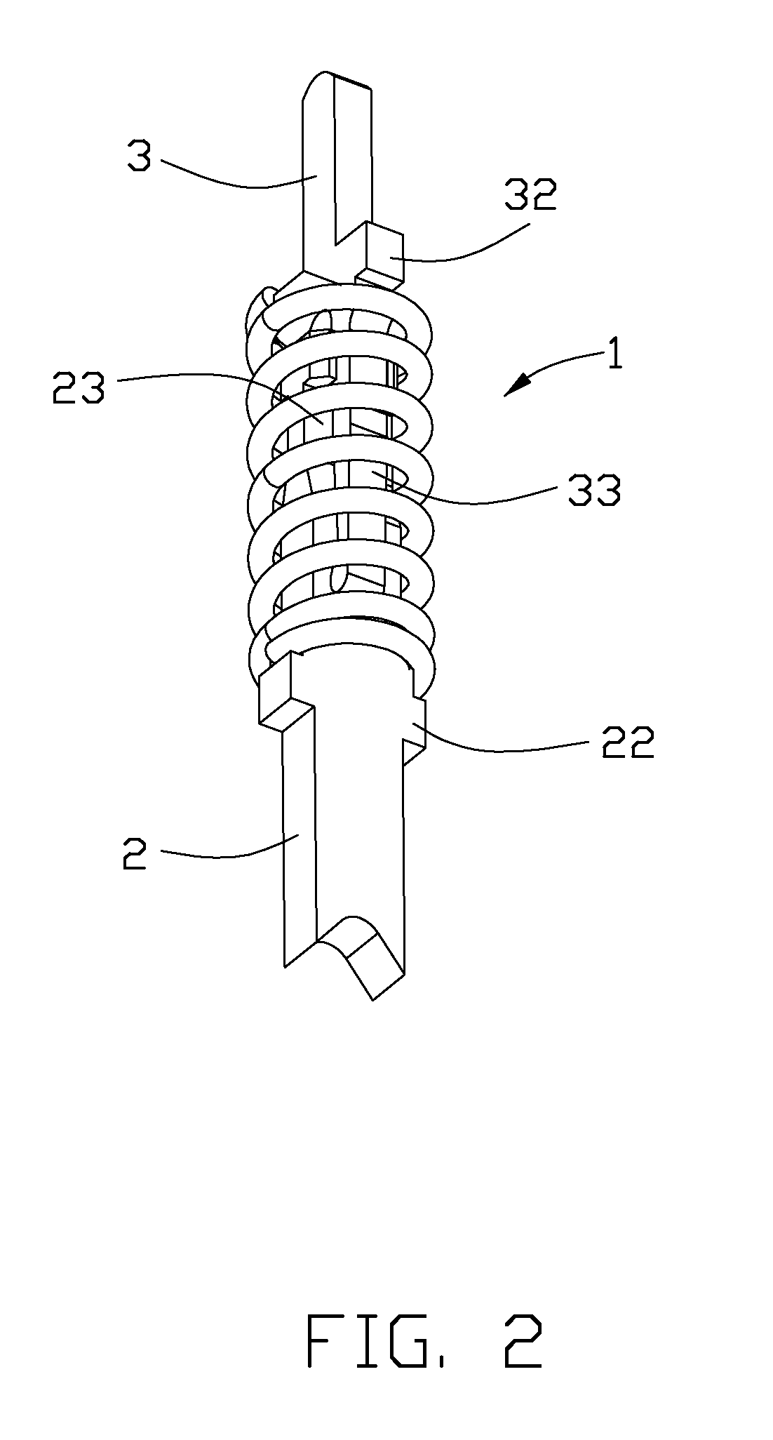
[0016]Reference will now be made in detail to the preferred embodiment of the present invention. Referring to FIGS. 1-5, a contact 1 applied in an electrical connector is mounted on a circuit board (not shown) and electrically connected with a chip (not shown). The contact 1 comprises a first contact pin 2, a second contact pin 3 and a coiled spring 4 surrounding the first contact pin 2 and the second contact pin 3.

[0017]The first contact pin 2 comprises a mating end 26, a body 23 and a mounting portion 21 opposite to the mating end 26 for being mounted on the circuit board. The first contact pin 2 includes a pair of opposite first side faces 201 and a pair of opposite second side faces 202. The first contact pin 2 further includes a pair of first blocking portions 22 protruding along a transverse direction from opposite first side faces 201.

[0018]The first contact pin 2 has a pair ear portions 24 proximate to the mating end 26 of the body 23. Each ear portion 24 is connected with t...


PUM


Abstract

A contact (1) includes a first contact pin (2), a second contact pin (3) and a spring (4). The first contact pin includes a mating end (26), a body (23) having a first body portion (232) and a second body portion (231), a pair of ear portions (24) and a pair of first blocking portions (22). The first body portion has a thickness greater than that of the second body portion. The second contact pin includes a pair of second blocking portions (32), and a pair of resilient beams (33) slidable between a latched position and an unlatched position. The resilient beams are confined by the ear portions. The resilient beams clasp the first body portion in the latched position. The spring is compressible between the pair of first blocking portions and the pair of second blocking portions.

Description

BACKGROUND OF THE INVENTION[0001]1. Field of the Invention[0002]The present invention relates to a contact, and more particularly to a compressible contact for electrical connector.[0003]2. Description of Related Art[0004]U.S. Pat. No. 7,025,602 issued to Hwang on Apr. 11, 2006 discloses a contact for electrical connector. The contact comprises a first contact pin having a pair of first hooks and a first beam, a second contact pin having a pair of second hooks and a second beam, and a coiled spring surrounding around the first and second contact pins. The coiled spring is compressed between a latched position and an unlatched position. The first hooks engage with the second hooks under a force generated along the mating direction at the unlatched position. The first hooks engage with the second beam and the second hooks engage with the first beam at the latched position.[0005]The first hooks and the second hooks could not engage with each other reliably. It is complicated to form th...

Claims


Application Information

Patent Timeline
Patent Type & Authority Patents(United States)
IPC IPC(8): H01R13/24
CPCH01R13/2421H01R13/2435
Inventor LIN, CHUN-FUCHEN, KE-HAO
Owner HON HAI PRECISION IND CO LTD
Why Eureka
Try Eureka