Apparatus and method for processing inside of pipe

a technology for processing apparatuses and pipes, applied in the direction of nuclear engineering, nuclear welding devices, nuclear elements, etc., can solve the problems of complex structure of processing apparatuses, inspection sensors that cannot perform desired inspection and examination, etc., to achieve accurate and correct movement in the inside of the pipe, simple arrangement, and simple construction

Active Publication Date: 2012-04-17
KK TOSHIBA
View PDF10 Cites 1 Cited by
  • Summary
  • Abstract
  • Description
  • Claims
  • Application Information

AI Technical Summary

Benefits of technology

[0014]An object of the present invention, which was made to solve the problems described above, is to provide an inside of pipe processing apparatus, which has a simple arrangement and a simple construction, can move in an inside of a pipe accurately and correctly without removing the pipe, can safely and securely perform works such as rinse, inspection, examination, planning maintenance, repair, and the like without damaging the pipe, and an inside of pipe processing method.
[0015]Another object of the present invention is to provide an inside of pipe processing apparatus, which does not damage a pipe in works such as rinse, inspection, examination, planning maintenance, repair, and the like without causing a worker to access an inside of the pipe in which a work environment is bad and the mounting / dismounting work of which to the pipe and the collection work of which from the pipe can be safely and easily performed, and an inside of pipe processing method.
[0042]According to the present invention, there can be provided the pipe inside processing apparatus, which has the simple arrangement and the simple construction, can accurately and correctly move in the inside of the pipe without removing the pipe, and can safely and securely perform the works such as rinse, inspection, examination, protective maintenance, repair and the like without damaging the pipe, and there can be also provided a pipe inside processing method.
[0043]Further, there can be provided the pipe inside processing apparatus, which does not damage a pipe in works such as rinse, inspection, examination, protective maintenance, repair, and the like without causing a worker to access an inside of the pipe in which a work environment is bad and the mounting or dismounting work of which to the pipe and the collection work of which from the pipe can be safely and easily performed, and also provided an pipe inside processing method.

Problems solved by technology

Further, since a person cannot access the pipe and a working environment cannot be secured, there is proposed a system (inspection without disassembly) for performing inspection and examination works by inserting a pipe inside processing apparatus into the pipe without removing an inlet mixer of the jet pump to reduce man-hour and working time.
Accordingly, there arises a problem in that the inspection sensor cannot perform desired inspection and examination.
Accordingly, it cannot perform desired inspection and examination.
Since it is necessary for an articulated arm having a multiplicity of degrees of freedom to correct the offset amount and to move the inspection sensor in the circumferential direction along the inside of the pipe, the structure of the processing apparatus is made complex and the size thereof is increased.
Thus, there arises a problem in that the apparatus cannot pass through the opening between a nozzle and a throat of the jet pump.
Furthermore, when the number of parts of the pipe inside processing apparatus is increased, there is a tendency that a risk of occurrence of failure also increases.
As a result, there is an increased risk that the arm cannot be closed because the pipe inside processing apparatus fails and cannot be collected from the opening between a nozzle and a throat of the jet pump.
Further, even if the processing apparatus can be collected, there is a high possibility of damaging the nozzle and the throat of the jet pump.

Method used


Image

  • Apparatus and method for processing inside of pipe
  • Apparatus and method for processing inside of pipe
  • Apparatus and method for processing inside of pipe

Examples


first embodiment

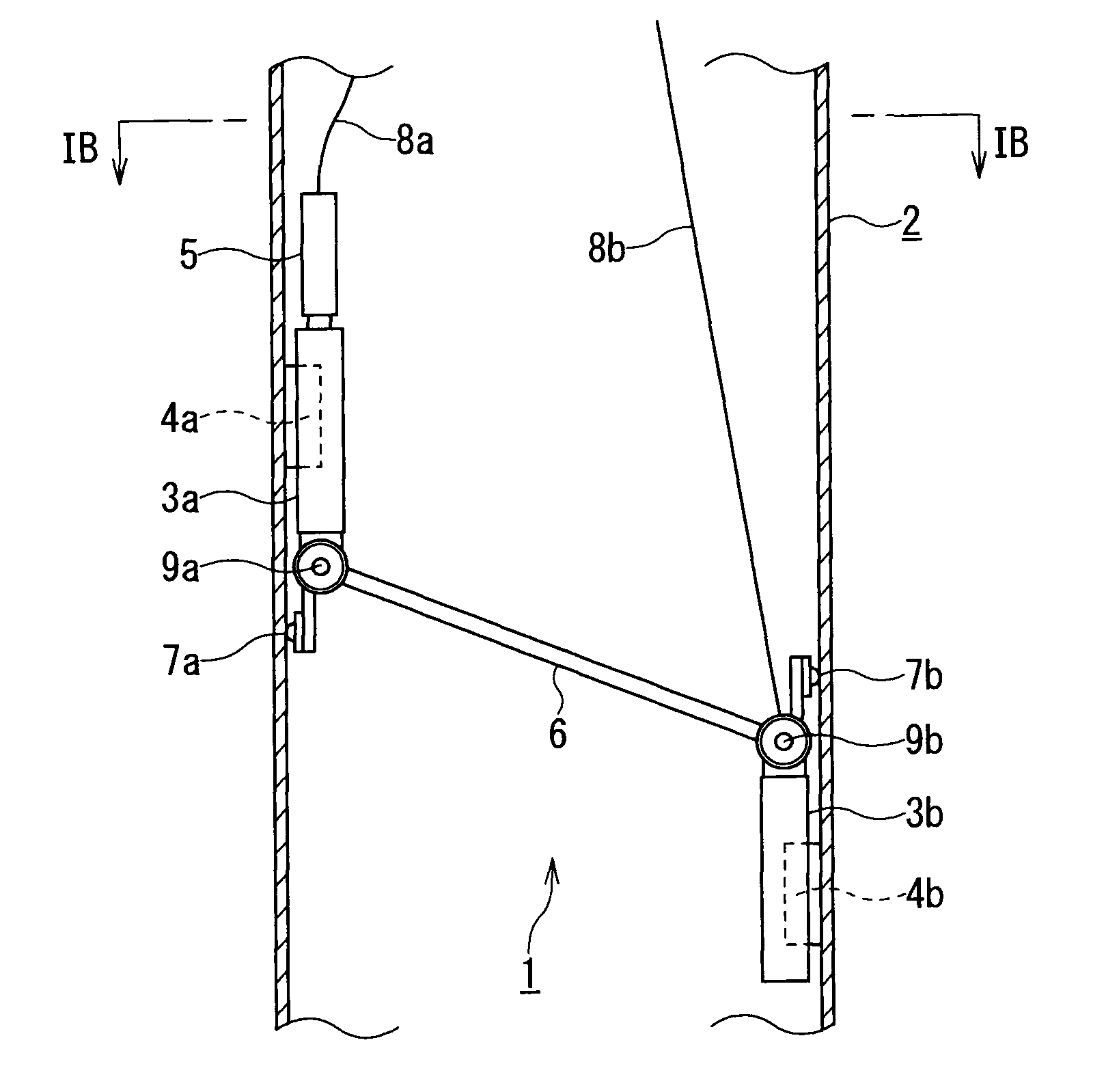
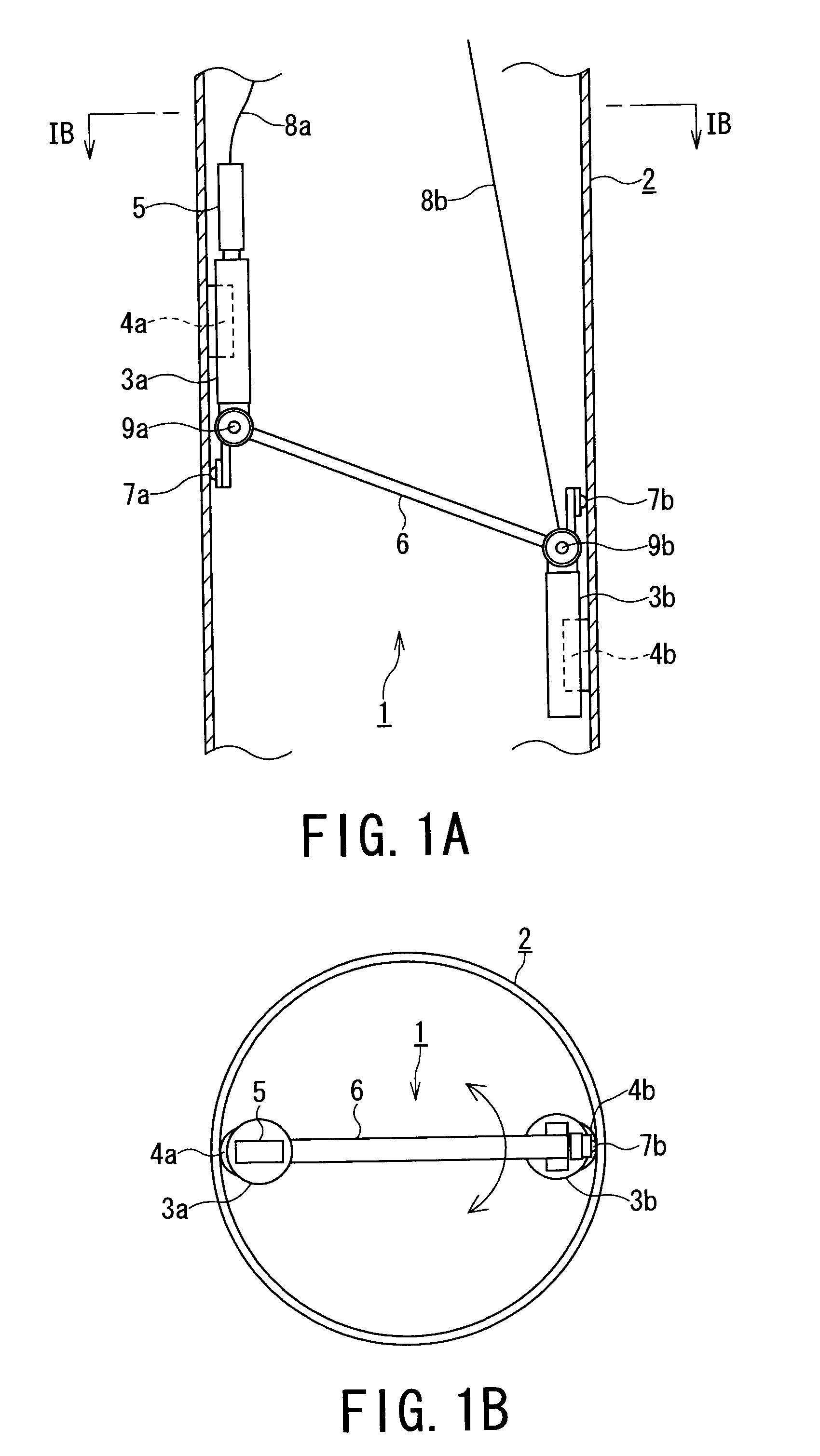
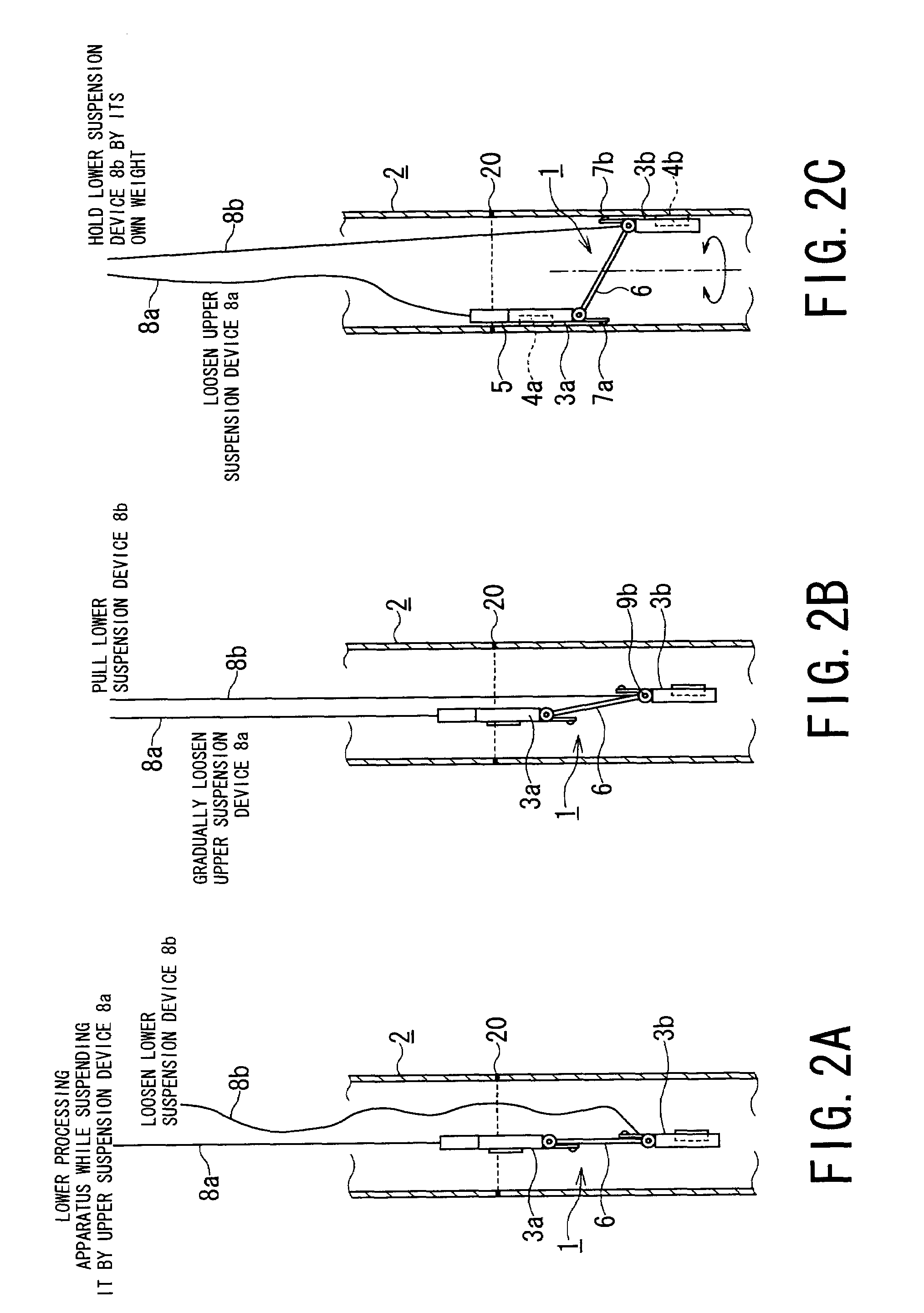
[0055]A first embodiment of an apparatus 1 for processing an inside of a pipe (called pipe inside processing apparatus, hereinafter) according to the present invention will be explained referring to FIGS. 1 to FIG. 5.

[0056]As shown in FIG. 1A, the pipe inside processing apparatus 1 of the first embodiment includes: traveling drive units 3a, 3b, which have traveling wheels 4a, 4b, respectively and move in a circumferential direction on an inside of a pipe (vertical pipe) 2 disposed such that the center axis thereof faces an approximately vertical direction; a working device 5 such as a phased array UT probe and the like which can search a crack in the pipe by an ultrasonic wave by, for example, a non-contact manner; a rotation support mechanism 9a disposed to the traveling drive units 3a; a rotation support mechanism 9b provided for the traveling drive units 3b; a coupling mechanism 6, which couples the traveling drive units 3a, 3b corresponding to each other so as to swing through t...

second embodiment

[0133]A second embodiment of the present invention will be explained hereunder with reference to FIGS. 6 and 7.

[0134]It is to be noted that, in the second embodiment, the same arrangements and structural elements as those of the first embodiment are denoted by the same reference numerals, and duplicated explanation is omitted herein.

[0135]FIG. 6A and FIG. 6B are front elevational view and plan view showing arrangement and shape of the pipe inside processing apparatus of the second embodiment according to the present invention.

[0136]As shown in FIG. 6A, the apparatus 1A for processing inside of pipe (pipe inside processing apparatus 1A) of the embodiment includes: a timing pulley 10a, which is fixed to a rotation support mechanism 9a; a timing pulley 10b, which is fixed to a rotation support mechanism 9b; and a timing belt 11, which connects the timing pulley 10a to the timing pulley 10b.

[0137]The timing pulleys 10a and 10b have the same shape.

[0138]In FIG. 7, the angle, at which th...

third embodiment

[0143]A third embodiment according to the present invention will be explained hereunder with reference to FIGS. 8A and 8B.

[0144]FIG. 8A and FIG. 8B are a front elevational view and a plan view showing arrangement and shape of a pipe inside processing apparatus 1B of the third embodiment according to the present invention.

[0145]In the third embodiment, the same elements or arrangements as those of the first embodiment are denoted by adding the same reference numerals, and duplicated explanation is omitted herein.

[0146]As shown in FIG. 8A, the pipe inside processing apparatus 1B of the present embodiment includes: traveling drive units 3a, 3b, 3c, which have traveling wheels 4a, 4b, 4c, respectively, to be movable in a circumferential direction on an inside of a vertical pipe 2; a working device 5, which is disposed to the traveling drive unit 3a; a rotation support mechanism 9a, which is disposed to the traveling drive unit 3a so that the attachment angle thereof is adjusted; a rotat...


PUM

PropertyMeasurementUnit
lengthaaaaaaaaaa
inner diameteraaaaaaaaaa
rotation angleaaaaaaaaaa

Abstract

An apparatus for processing an inside of a pipe which performs various works from an inside of a pipe, includes traveling drive units, a working device, rotation support mechanisms, a coupling mechanism, and suspension devices. The traveling drive units are inserted into the inside of the pipe, and the working device is moved in a circumferential direction along the inside of the pipe by the traveling drive units.

Description

BACKGROUND OF THE INVENTION[0001]1. Field of the Invention[0002]The present invention relates to an apparatus for processing an inside of pipe and a method of processing an inside of pipe for performing works such as rinse, inspection, examination, preventive maintenance, repair, and the like of an inside of a pipe, and, more particularly, to an apparatus and method for processing an inside of pipe for performing necessary works such as rinse, inspection, examination, preventive maintenance, repair, and the like of an inside of a pipe with respect to a welding line of a jet pump installed in a pressure vessel of a boiling water reactor.[0003]2. Related Art[0004]Works such as rinse, inspection, examination, preventive maintenance, repair, and the like of an inside of a pipe in a jet pump installed in a pressure vessel of a boiling water reactor must be performed under radiation environmental conditions. Further, since a person cannot access the pipe and a working environment cannot b...

Claims


Application Information

Patent Timeline
Patent Type & Authority Patents(United States)
IPC IPC(8): B08B9/045B08B13/00B23K28/00B24B7/00B23K26/00B23K9/00B25J5/00G21C19/02
CPCB23K37/02B24B5/40B24B39/02G21C17/017B23K2201/06G21C15/25G21Y2002/304G21Y2004/501G21Y2004/504B23K2101/06Y02E30/30
Inventor SHIMAMURA, MITSUAKITOGASAWA, YUTAKAMAEHARA, TAKESHIYUGUCHI, YASUHIRO
Owner KK TOSHIBA
Why Eureka
Try Eureka