Method and apparatus for mura detection and metrology

a detection method and metrology technology, applied in the field of quality control, can solve the problems of affecting the quality of mura detection,

Inactive Publication Date: 2012-04-17
MICRONIC LASER SYST AB
View PDF17 Cites 32 Cited by
  • Summary
  • Abstract
  • Description
  • Claims
  • Application Information

AI Technical Summary

Problems solved by technology

Each measured site may take several seconds and a job with several thousand sites takes several hours.
Mura areas are often areas containing errors that are missed by defect inspection and metrology, errors which have a magnitude far below the detection limit of the defect inspection system, sometimes also below the accuracy of the metrology system, but which affect many features within the area, making that area on average visibly different from the neighborhood.
It requires an extremely low detection limit, often below the stability of the sensor, sometimes even below the noise floor.
The noise floor may be due to instrument noise, in which case a more sensitive sensor might be possible, but more often the noise floor is due to randomness in the workpiece.
Furthermore, electronic malfunctions are usually due to isolated errors, e.g. line width errors, while in visual displays the errors are averaged over some area by the visual system.
This is not an ideal test method.
It is non-quantitative, forcing the inspection person to be very conservative in their judgment.
The method is very sensitive for certain types of errors and not for other types.
Inter-layer errors go largely untested and undetected.
Moreover, while it is sensitive to line width and edge quality, it is only sensitive to sharp steps in the placement of features, thereby largely missing interlayer effects.

Method used


Image

  • Method and apparatus for mura detection and metrology
  • Method and apparatus for mura detection and metrology
  • Method and apparatus for mura detection and metrology

Examples


Embodiment Construction

[0030]The following detailed description is made with reference to the figures. Preferred embodiments are described to illustrate the present invention, not to limit its scope, which is defined by the claims. Those of ordinary skill in the art will recognize a variety of equivalent variations on the description that follows.

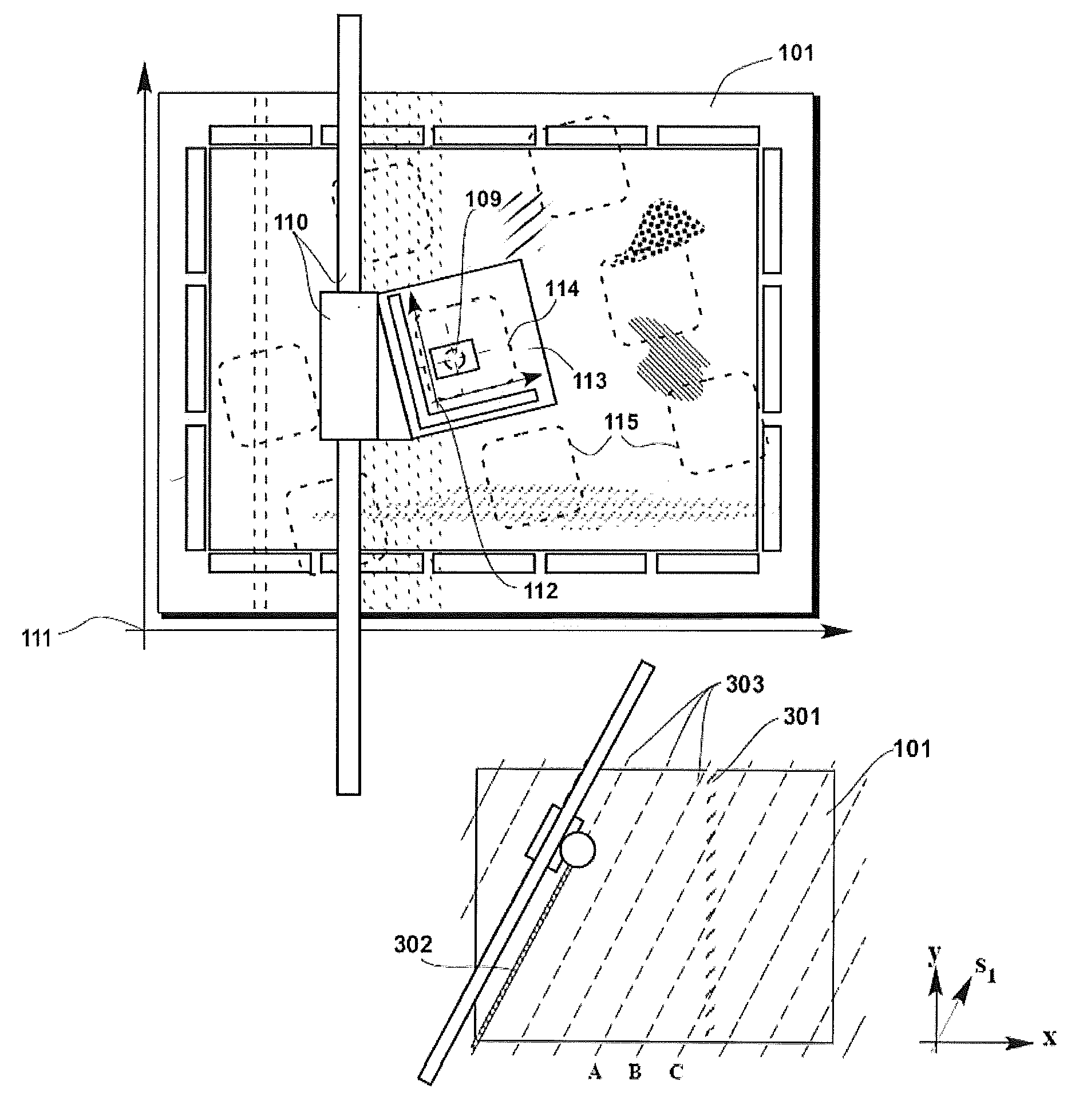
[0031]The underlying errors causing the mura may be of many kinds, only some of which have been recognized or understood in the art. One cause is a variation in the open or light sensitive areas, e.g. a variation in the width of the black matrix masking the transistor and the boundary between pixels in an LCD display. Every pixel in an active display has at least one transistor with a gate which is much smaller than the size of the LCD pixel, thereby being much more sensitive to line width variations. The edge profile of the different layers may also vary and give rise to mura. Line width, shape and edge variations are intra-layer effects, i.e. they can be detect...


PUM


Abstract

The invention addresses the lack of comprehensive and quantitative methods for measurements of unwanted visual “mura” effects in displays and image sensors. Mura is generated by errors that are significantly smaller than what is needed for the function of the device, and sometimes smaller than the random variations in the patterns or structures. Capturing essentially all mura defects in a workpiece in a short time requires a daunting combination of sensitivity, statistical data reduction and speed. The invention devices an inspection method, e.g. optical, which maximizes the sensitivity to mura effects and suppresses artifacts from the mura inspection hardware itself and from noise. It does so by scanning the sensor, e.g. a high-resolution camera, creating a region of high internal accuracy across the mura effects. One important example is for mura related to placement errors, where a stage with better than 10 nanometer precision within a 100 mm range is created. A sampling scheme reduces the data volume and separates between instrument errors and real defects based on their different geometrical signatures. The high-resolution camera scans sparse lines at an angle to the dominating directions of expected mura defects, creating extended sensor fields with high internal precision, and quantifying edge placements in small windows in said extended fields. The mura is classified and presented as type, location and severity.

Description

RELATED APPLICATIONS[0001]This application claims priority to two related provisional U.S. Patent Applications: No. 60 / 912,485 entitled “METHOD AND DEVICE FOR MURA INSPECTION” by inventor s Torbjörn Sandström and Lars Stiblert filed on 18 Apr. 2007; and No. 60 / 988,413 entitled “METHOD AND APPARATUS FOR MURA DETECTION AND METROLOGY” by inventor Torbjörn Sandström filed on 15 Nov. 2007. The provisional applications are hereby incorporated by reference.BACKGROUND OF THE INVENTION[0002]This disclosure relates to quality control in the production of extremely accurate patterns, such as those in visual displays (LCD, OLED, SED, FED, PDP, and similar well known display technologies) and image sensors (CCD, CMOS, and other technologies.) The analyzed workpieces may be solid or flexible, and they may be analyzed from the front side or back side. They may be protected by pellicles or other clear sheets at the time of optical analysis. In particular, it provides methods and apparatuses for the...

Claims


Application Information

Patent Timeline
Patent Type & Authority Patents(United States)
IPC IPC(8): G06K9/00
CPCG01N21/956G06T7/0006G06T7/001G01N2021/9513G06T2207/30121G06T2207/30148G06T2207/30164G02F1/1309G03F1/84G02F1/13G06F1/00
Inventor SANDSTROM, TORBJORNSTIBLERT, LARS
Owner MICRONIC LASER SYST AB
Why Eureka
Try Eureka