Modular counterweight carriage for cranes, in particular for large crane

a crane and module technology, applied in the direction of cranes, etc., can solve the problems of large counterweight, inability to raise ballast, and inability to achieve the ballast weight required to achieve high lifting capacity

Active Publication Date: 2012-04-24
TADANO DEMAG GMBH
View PDF21 Cites 18 Cited by
  • Summary
  • Abstract
  • Description
  • Claims
  • Application Information

AI Technical Summary

Benefits of technology

[0013]The task of the present invention is to provide a modular counterweight system which offers the maximum superlift counterweight for the crane in question without requiring a correspondingly large carriage, where the mobility of the crane continues to be guaranteed.

Problems solved by technology

So that large loads can be lifted, a relatively large counterweight must be provided because of the basic machine's complete or almost complete the lack of contribution to the stability moment.
The disadvantage of the non-traveling ballast arrangements is that, in the case of small-to-medium loads, it is not always possible to raise the ballast, and in the case of derrick cranes it is not usually allowable to do so.
The high ballast weights required to achieve high lifting capacities, however, require large-sized, complicated, and expensive traveling designs.
Both solutions are complicated, expensive, and hardly suitable for application to small cranes.

Method used


Image

  • Modular counterweight carriage for cranes, in particular for large crane
  • Modular counterweight carriage for cranes, in particular for large crane
  • Modular counterweight carriage for cranes, in particular for large crane

Examples


Embodiment Construction

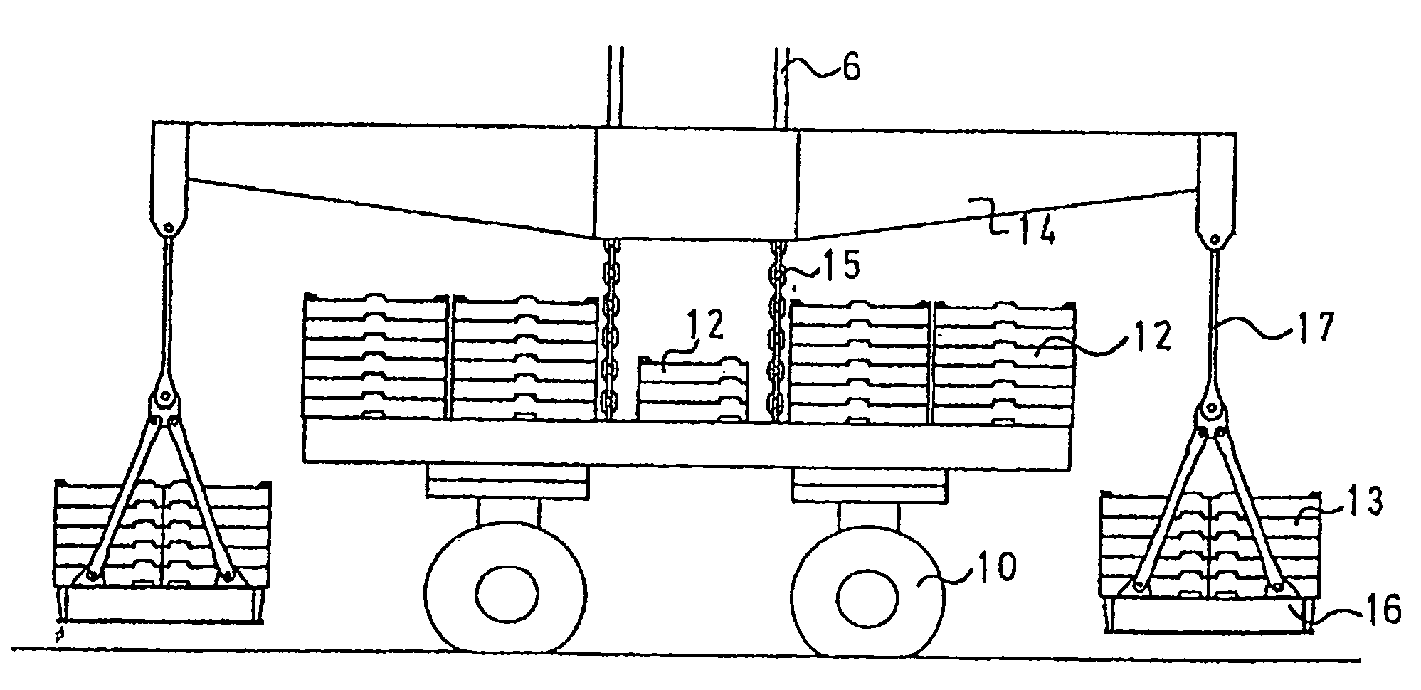
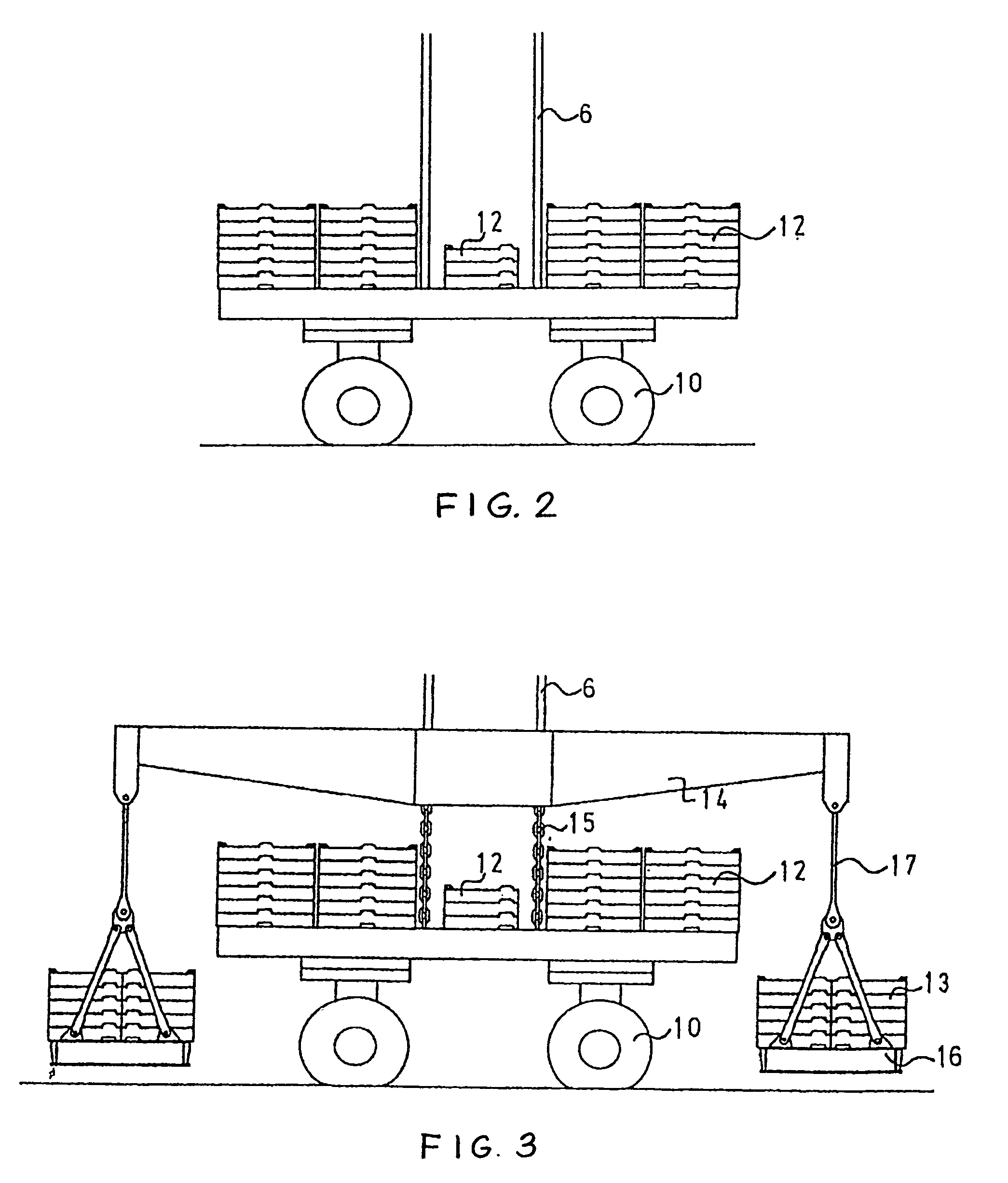
[0033]In the present case, a solution made up of existing traveling components and existing or specially designed non-traveling counterweight components is used.

[0034]Referring to FIG. 3, a crossbeam 14 is provided above the traveling counterweight 12. This crossbeam is connected in the upward direction to the tip of the derrick boom 2 by carrier rods 6, and in the downward direction both to the traveling counterweight 12 and also to the non-traveling counterweight 13.

[0035]The connection between the crossbeam 14 and the traveling counterweight 12 is designed in such a way that the non-traveling counterweight 13 is lifted first, before the traveling counterweight 12 is activated. A simple design consists of a chain 15 between the crossbeam 14 and the traveling counterweight carriage 9, the length of the chain 15 being calculated so that it does not become taut until after the non-traveling counterweight 13 has been lifted. Alternatively, rods with a joint or a pin in a slot can be p...


PUM


Abstract

A large mobile crane includes a revolving superstructure, a main boom hinged to the superstructure, and a derrick boom hinged to the superstructure. A modular counterweight system includes a traveling counterweight and a non-traveling counterweight connected to a crossbeam suspended from the distal end of the derrick boom so that the non-traveling counterweight is activated before the traveling counterweight.

Description

CROSS-REFERENCE TO RELATED APPLICATIONS[0001]This is a U.S. national stage of International Application No. PCT / DE2006 / 001844, filed on 13 Oct. 2006. Priority is claimed on German Application No. 10 2005 055 693.0, filed on 17 Nov. 2005, and German Application No. 10 2006 010 488.9, filed on 1 Mar. 2006.BACKGROUND OF THE INVENTION[0002]1. Field of the Invention[0003]The invention pertains to all cranes equipped with counterweight carriages, especially to large cranes with a superstructure, with at least one main boom and at least one derrick boom, and with a separate counterweight connected to the tip of the derrick boom.[0004]2. Description of the Related Art[0005]The invention can be used for various types of cranes. These will be explained briefly in the following. In all cases, a main boom 1 and a derrick boom 2 are hinged to a common structure, which is referred to as the superstructure 3. In the case of an inventive crane, the superstructure 3 can move with at least one degree...

Claims


Application Information

Patent Timeline
Patent Type & Authority Patents(United States)
IPC IPC(8): B66C23/76
CPCB66C23/74
Inventor ZOLLONDZ, RUDIGERWECKBECKER, ALFONSKOSTER, FRITZ-BOTHOKARP, GUNTERFRANZEN, HANS-PETER
Owner TADANO DEMAG GMBH
Why Eureka
Try Eureka