Explosive substance destroy machine and special warhead thereof

A technology of explosives and warheads, applied in the directions of warheads, ammunition, projectiles, etc., can solve the problems of skill discount, weakened recoil, complicated operation process, etc., and achieve the effect of low production cost and simple structure

Inactive Publication Date: 2008-04-09
杨德智
View PDF1 Cites 9 Cited by
  • Summary
  • Abstract
  • Description
  • Claims
  • Application Information

AI Technical Summary

Problems solved by technology

[0007] The shock absorbing and buffering design of this explosive destroyer is relatively simple. Since the propellant cartridge is fired from the top to the bottom, the high-pressure gas generated by it shoots downward to the conical water separation body, producing two water streams sprayed from the front and rear directions: one A branch of water flows forward from the launch tube to produce a high-pressure jet to attack suspicious explosives, but the high-pressure gas produced by the launch cartridge turns 90° from top to bottom through the conical water body and then shoots horizontally, and its power is greatly reduced; Finally, water is shot out from the two anti-retraction pipes to reduce the recoil force. The water in the anti-retraction pipes shoots far to the rear, which is very unfavorable to the operation
At the same time, the anti-retraction tube cannot completely absorb the recoil force generated by the firing of the device, causing the device to move backward or fall over after firing, which cannot completely solve the problem
Therefore, there are serious safety hazards when the public security, armed police, and military units in our country use the above two explosives destroyers.
[0008] There are similar explosives destroyers in foreign countries. The operation process is very complicated, and the price is as high as 280,000 yuan.

Method used


Image

  • Explosive substance destroy machine and special warhead thereof
  • Explosive substance destroy machine and special warhead thereof
  • Explosive substance destroy machine and special warhead thereof

Examples


Embodiment 1

[0060] Embodiment 1 explosive destroyer

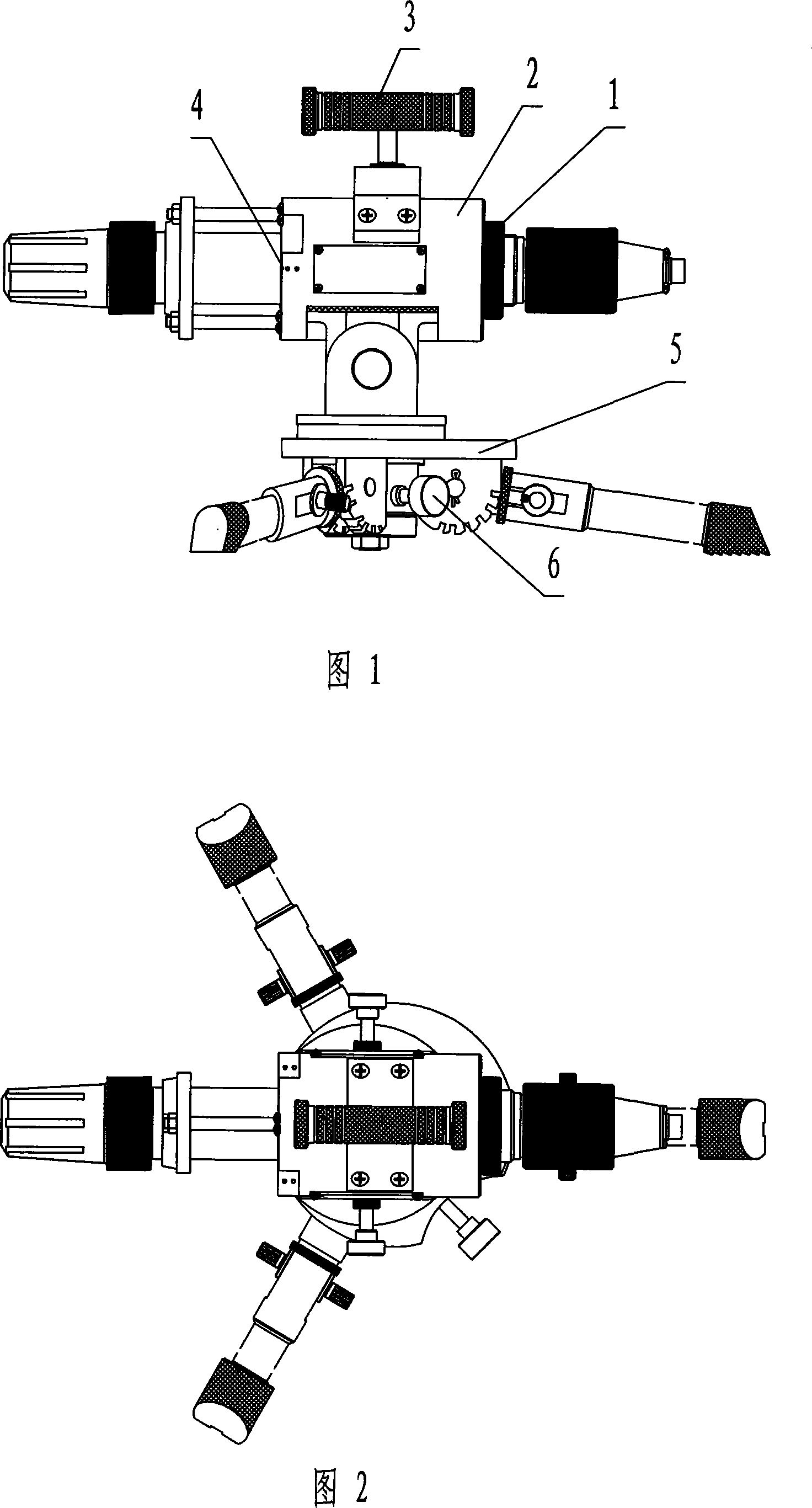
[0061] The main components of the explosive destroyer of the present invention are shown in Fig. 1 . It consists of a launcher 1, a buffer seat 2 socketed outside the launcher 1, a handle 3 installed on the upper part of the buffer seat 2, a two-way laser sight 4 installed on the side of the buffer seat 2, and connected to the lower part of the buffer seat 2. The tripod type supporting device 5 and the locking hand wheel 6 are composed.

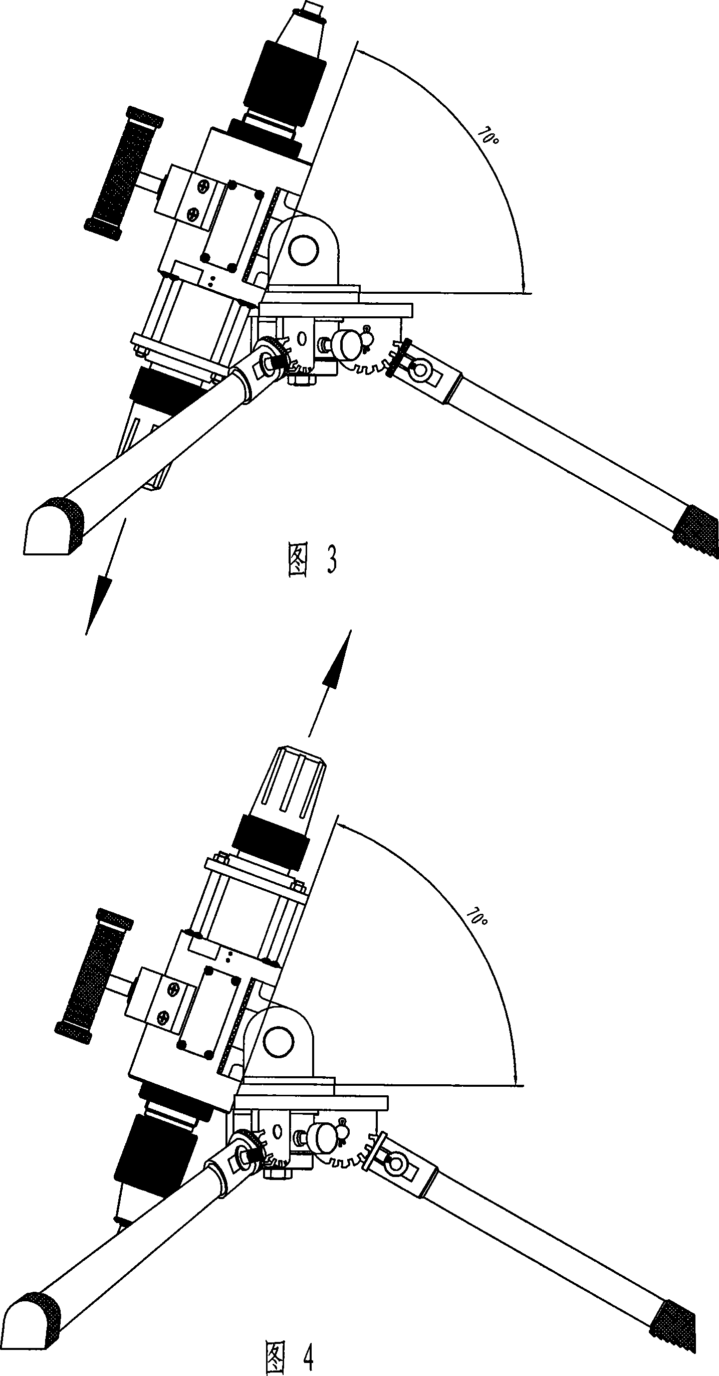
[0062] By adjusting the locking handwheel 6, the launching device 1 can be rotated arbitrarily on the supporting device 5 at 360° in the horizontal direction and 70° in the up and down directions without jamming. When positioning, it is locked by the locking handwheel 6, as shown in Figure 2, 3, 4 shown.

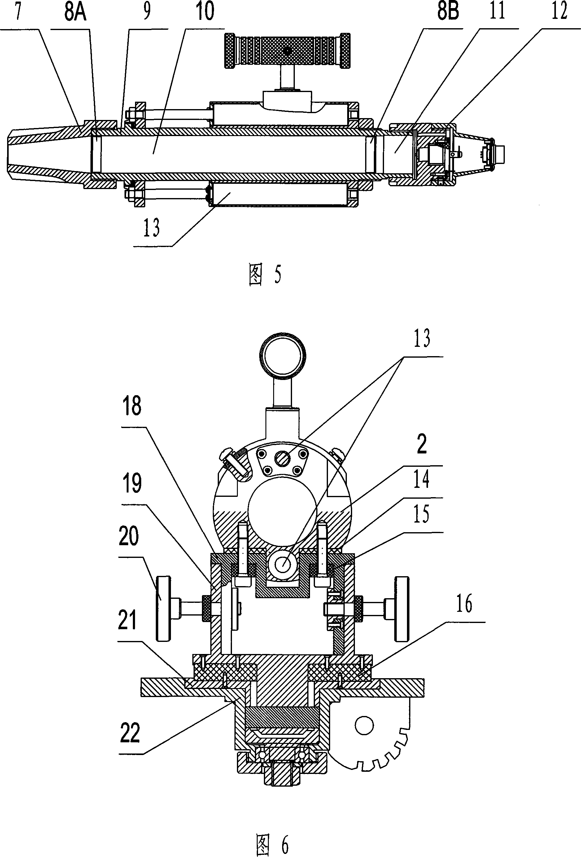
[0063] Fig. 5 is a detailed structural diagram of the transmitting device. Whole launching device 1 is made up of launch tube 9, taper-shaped faucet 7 installed on the front end of launch tube 9...

Embodiment 2

[0072] Embodiment 2 Explosive Destroyer Dedicated Submunition

[0073] The 38mm conical submunition is shown in Figure 14. Wherein, the tapered bullet tip 41 made of steel is fastened on the plexiglass cone 42 to form a sub-body, and the cone 42 rear has a hollow cylinder whose size is just enough to be inserted into the plexiglass matrix 43 . The shape of the mother body 43 is hollow in the front cone and the back circle, and an elastic sealing ring 44 is arranged on the cylinder at the rear part of the mother body 43 .

[0074] Take off water nozzle 7 during application, replace front end water plug 8A with this conical submunition and be installed in launch tube 9 front ends, fill into water in launch tube 9. By triggering the explosive destroyer, the submunition can penetrate steel plates or thicker wooden boards up to 2mm thick, and can also destroy the packaging of explosives that are difficult for water bombs to penetrate and disintegrate. When the design of this su...

Embodiment 3

[0075] Embodiment 3 Special Bullet for Explosive Destroyer

[0076] Steel bullets are shown in Figures 15 and 16. The conical attack warhead 45 is processed by stainless steel, and its front end is a truncated cone, and the hollow part is processed into a cylindrical shape. Its rear portion is provided with the guide body 46 of three lobe plastic moldings, and its external diameter is consistent with launch tube 9 internal diameters.

[0077] During application, the conical attack warhead 45 and the guide body 46 are inserted into the launch tube 9 together. No water is poured into the launch tube 9, and when the explosive destroyer fires, the electric projectile 11 produces high-pressure gas to push the conical attack warhead 45 and the guide body 46 to shoot forward at high speed, and then the three-lobe guide body 46 falls off, and the conical attack Warhead 45 flies forward. Tests have proved that it can break through the packaging of hard explosives such as cast iron...


PUM

PropertyMeasurementUnit
Caliberaaaaaaaaaa

Abstract

The invention provides an explosive destroying machine and a special warhead and comprises a supporting device (5) and an electropult (1) which is arranged on the supporting device (5), wherein, the electropult (1) comprises a transmitting valve (9), a front-end water line plug (8A) and a back-end water line plug (8B), a water faucet (7), an electric projectile (11) and an electric portfire (12); a buffer seat (2) is arranged between the supporting device (5) and the electropult (1) and a multi-level buffer device is arranged in the buffer seat (2). The explosive destroying machine has no recoil, far shooting range, wide use, moreover simpler structure and lower manufacture cost.

Description

technical field [0001] The invention relates to explosive destruction equipment, in particular to an explosive destruction device and a special warhead thereof. Background technique [0002] Explosive destroyer (also known as water gun, water cannon gun) is a kind of explosive or unknown suspicious items that are used to directly destroy simple packaging that is difficult for someone to dismantle directly, so as to protect personal safety. Widely used in counter-terrorism operations. This kind of explosive destroyer is generally composed of a launching device and a supporting device. Its principle is generally driven by gunpowder, ammunition or compressed gas, so that the water will generate an extremely fast speed and be ejected in the form of a high-pressure jet to hit the target object. , directly smash or destroy the detonating device, explosives and outer packaging, and at the same time cover and wet it with water without detonating, so as to achieve the purpose of des...

Claims


Application Information

Patent Timeline
IPC IPC(8): F41F1/00F42B30/00
Inventor 杨德智
Owner 杨德智
Why Eureka
Try Eureka