Inkjet printing head and inkjet printing cartridge

a technology of inkjet printing and inkjet printing, which is applied in the field of inkjet printing head and inkjet printing cartridge, can solve the problems of unstable ink ejection, unsmooth ink ejection after interruption of ink ejection for a while, and increase the cost of printing, so as to avoid the complexity of structure and/or control, the effect of suppressing the cost ris

Inactive Publication Date: 2012-04-24
CANON KK
View PDF14 Cites 3 Cited by
  • Summary
  • Abstract
  • Description
  • Claims
  • Application Information

AI Technical Summary

Benefits of technology

[0016]The present invention is directed to an inkjet printing head and an inkjet printing cartridge capable of ejecting miniaturized ink droplets in a stable manner while suppressing the cost rise as well as avoiding the complexity of the structure and / or the control.
[0017]According to an aspect of the present invention, there is provided an inkjet printing head including an ink ejecting section having a plurality of ejection openings configured to eject a plurality of kinds of inks at different ejection amounts, a common ink chamber provided with respect to the respective kind of ink and configured to supply the ink to the plurality of ejection openings, and ink supply paths facilitating supplying the respective ink to the common ink chamber. The ink supply path for the ink ejected from the ejection opening having a relatively small ejection amount is adjacent to the another ink supply path via a wall.
[0019]According to the present invention, in a path for supplying ink from an ejection opening capable of ejecting a relatively small amount of ink in a group of a plurality of ejection openings, an amount of moisture evaporated from the ink is restricted. Thereby, it is possible to obtain an inkjet printing head and an inkjet printing cartridge capable of restricting the deterioration of the ejection easiness in the ejection opening having a small ejection amount, suppressing the cost rise, avoiding the complexity of structure or control and ejecting miniaturized ink droplet in a stable manner.

Problems solved by technology

In such a printing head, since the ink is in contact with outer air via the ejection openings, there may be a risk in that the moisture in the ink evaporates to increase the ink viscosity.
If the ink viscosity increases in such a manner, there may be a risk in that the ejection of ink becomes unstable.
Particularly, first ink ejection after the interruption of ink ejection for a while becomes unsmooth since the ink viscosity increases in the vicinity of the ejection opening due to the evaporation.
That is, when an interval between the succeeding ejections becomes long, the moisture in the ink in the vicinity of the ejection opening evaporates to worsen the easiness of ink ejection.
If the state of ejection changes in such a manner due to the variation of the ejection interval, there may be a risk in that the printing on a medium is also variable to lower the printing quality.
Since the colorant concentration changes if the moisture in ink evaporates via the ejection opening or the resin forming the ink storage section, there is a risk in that the color density or color tone of the recording printed on a printing medium changes to worsen the quality of the recording.
If the driving energy to be applied to the heat element is reduced, the easiness of the ejection becomes worse after a predetermined period has passed since the amount of ejected ink as well as the ejection speed is lowered.
Also, if the open area of the ejection opening is minimized, a flow resistance of the ink to be ejected increases to worsen the easiness of ejection after the passage of the predetermined time interval.
Namely, while the easiness of ejection is worsened by the evaporation of moisture in ink after the passage of the predetermined time interval as described before, it is also worsened by the reduction of the driving energy applied to the heat element or the minimization of the open area of the ejection opening.
If the driving energy applied to the heating element is reduced, however, it is difficult to restrict the deterioration of the ink ejection caused by the deceleration of the ink-ejection speed after the predetermined time passage unless any means is taken.
Also, when the open area of the ejection opening is minimized, it is difficult to restrict the deterioration of the ejection easiness after the predetermined time passage due to the increase of the flow resistance unless any means is adopted as described hereinabove.
Accordingly, as the ink droplet is smaller, the ejection easiness after the predetermined time has passed becomes worse, which results in the increase in the number of the preliminary ejection as well as an amount of ink not contributed to the printing operation.
This causes a risk of increase in cost due to the increase in amount of contained ink, or increase in the running cost due to the reduction of an amount of ink usable by the user for the printing operation.
H6-126955, since the valve is provided in the respective ejection opening, the cost is extremely high.
Whereby, if the number of ejection openings is increased for the purpose of accelerating the printing speed, further rise in the cost is expected.
There is a risk, however, in that, if it is desired to increase kinds of ink or the number of ejection openings, items to be controlled increase, resulting in the complexity of the structure and / or control.

Method used


Image

  • Inkjet printing head and inkjet printing cartridge
  • Inkjet printing head and inkjet printing cartridge
  • Inkjet printing head and inkjet printing cartridge

Examples


first embodiment

[0037]A first embodiment according to the present invention will be explained below with reference to the attached drawings.

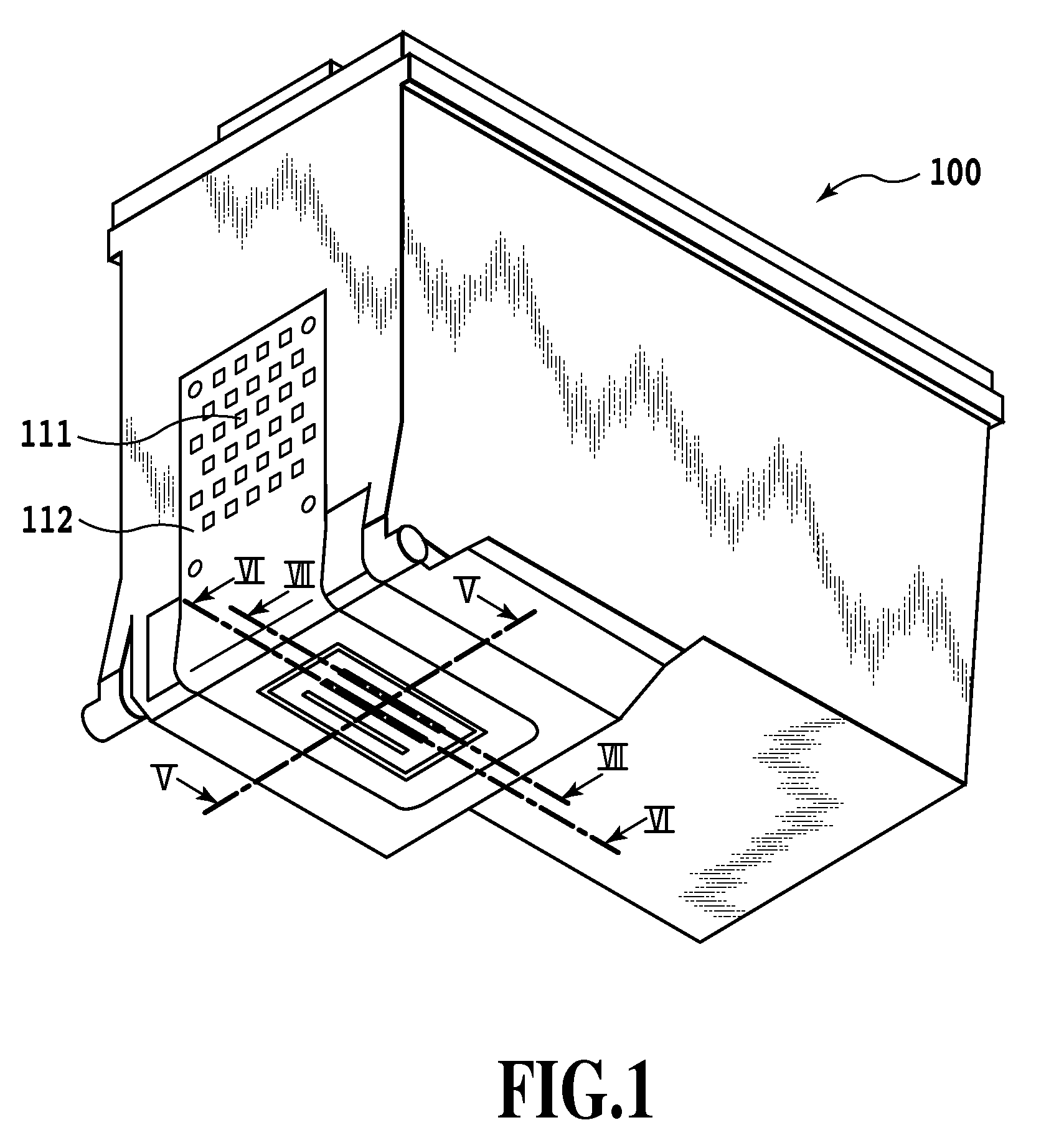
[0038]FIG. 1 is a perspective view illustrating an appearance of an inkjet printing cartridge 100 according to this embodiment. An inkjet printing head 101 carrying out the printing operation by ejecting ink is provided in an ink ejecting section at a lower position of the inkjet printing cartridge 100. On the side surface of the inkjet printing cartridge 100, a contact section 111 having electric contacts for receiving driving signals or other from an inkjet printing device (not shown) is provided. The contact section 111 and the inkjet printing head 101 are electrically connected to each other via an electric wiring tape 112.

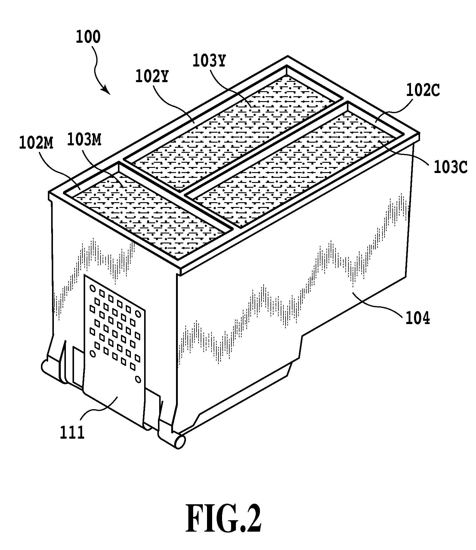
[0039]FIG. 2 is a perspective view illustrating the inkjet printing cartridge 100 from which is removed a tank cap. The inkjet printing cartridge 100 according to this embodiment is capable of storing a plurality of kinds of ink: cyan, ma...

second embodiment

[0064]A second embodiment of the present invention will be described below with reference to FIGS. 9 to 15.

[0065]FIG. 9 is a perspective view of the appearance of an inkjet printing cartridge 200 in this embodiment. The appearance of the inkjet printing cartridge 200 is approximately the same as the inkjet printing cartridge 100 in the first embodiment. Only one difference between the two is that, while the inkjet printing head 101 in the first embodiment has six rows of ejection openings (corresponding to three colors), that in this embodiment has eight rows of ejection openings (corresponding to four colors).

[0066]FIG. 10 is a perspective view of the inkjet printing cartridge 200 illustrating a state wherein a tank cap is removed therefrom. The inkjet printing cartridge 200 according to this embodiment has a structure wherein each of cyan (C), magenta (M), yellow (Y), and black (B) inks has an ink storage section and an ink supply path. The ink printing cartridge 200 has ink stora...

third embodiment

[0079]A third embodiment of the present invention will be described below with reference to the attached drawings.

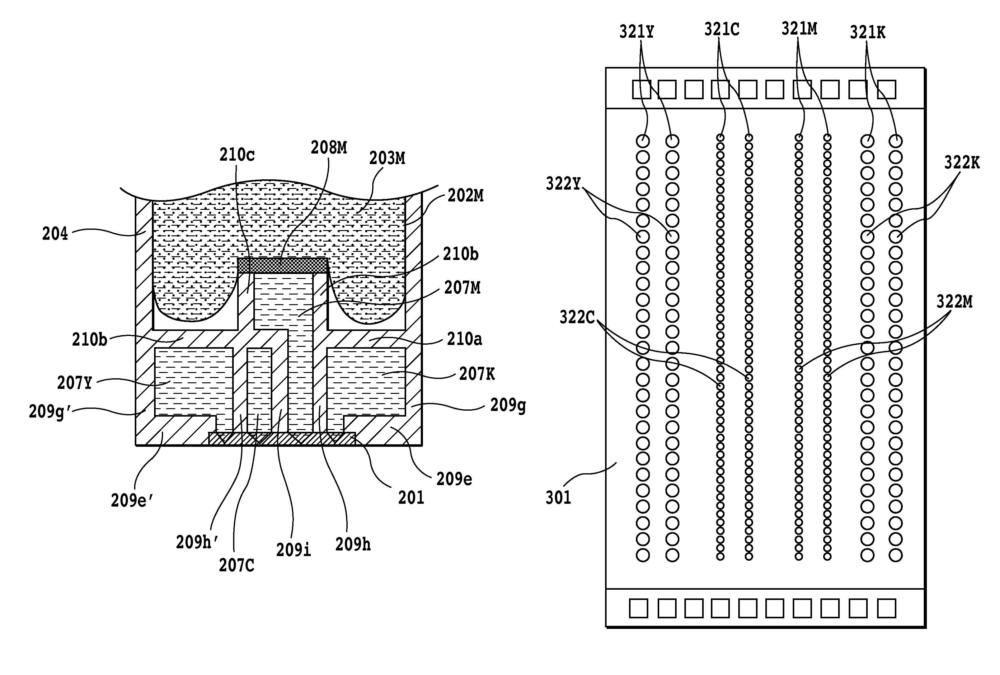
[0080]FIG. 16 is a plan view of an inkjet printing head 301 according to this embodiment. Only one difference in structure of this embodiment from that of the second embodiment is the arrangement of rows of ink ejection openings in the inkjet printing head 301. That is, the rows 221Cb and 221Mb of the ejection openings in the second embodiment (see FIG. 11) are changed to rows 321C and 321M of small ejection openings to increase the number of ejection openings. Since the other construction is the same as in the second embodiment, the explanation thereof will be eliminated.

[0081]According to this embodiment, the row of ejection openings for ejecting cyan and magenta inks uses no large ejection openings, but solely consists of small ejection openings. Also, since the number of ejection openings 322C and 322M are larger than those of the other ejection openings 321Y and 321...


PUM


Abstract

An inkjet printing cartridge capable of ejecting miniaturized ink droplets in a stable manner while avoiding the complexity of the structure and control as well as suppressing the cost rise. For this purpose, the inkjet printing cartridge is formed of a material having the permeability to liquid and gas, and the ink supply path for supplying ink to the ejection opening having a relatively small ejection amount is arranged adjacent to other ink supply paths via walls.

Description

BACKGROUND OF THE INVENTION[0001]1. Field of the Invention[0002]The present invention relates to an inkjet printing head and an inkjet printing cartridge applicable to a printing device for carrying out the printing by ejecting liquid such as ink.[0003]2. Description of the Related Art[0004]Printing heads used for an inkjet printing device for carrying out the printing by ejecting ink are classified to several kinds in accordance with methods for ejecting ink. Of them, a printing head of a thermal system applies a driving energy to a heat element to generate the film boiling in ink, resulting in the ejection of ink from an ejection opening due to a pressure caused by the film boiling to complete the printing.[0005]Generally, the printing head includes a plurality of ejection openings for ejecting ink, ink paths communicated with these ejection openings, and heating elements arranged opposite to the ejection openings. Further, the printing head has rows of ejection openings wherein a...

Claims


Application Information

Patent Timeline
Patent Type & Authority Patents(United States)
IPC IPC(8): B41J2/175B41J2/05B41J2/21
CPCB41J2/17513B41J2/1753B41J2/17553
Inventor AMMA, HIROMASATSUKUDA, KEIICHIRO
Owner CANON KK
Why Eureka
Try Eureka