Adjustable cable tray joint

a cable tray and adjustment technology, applied in the direction of couplings, curtain suspension devices, machine supports, etc., can solve the problems of inability to achieve the range of angular relationships between adjacent runs of cable tracks, the installation of a cable tray may encounter previously installed obstacles, and the work is labor intensive and time-consuming

Active Publication Date: 2012-05-01
JAMES C WHITE CO INC
View PDF32 Cites 31 Cited by
  • Summary
  • Abstract
  • Description
  • Claims
  • Application Information

AI Technical Summary

Problems solved by technology

However, in other applications, the installation of a run of cable tray may encounter previously-installed obstacles, such as pipes, conduit, or even other cable tray runs, residing in the same plane as the cable tray being installed.
Such work has been found to be labor intensive and time consuming, and undesirable.
No pivoting between adjacent sections of a cable track is contemplated, and therefore no range of angular relationships between adjacent runs of cable track may be accomplished.
The apparatus accomplishes such avoidance, however, with the use of pre-configured, fixed geometry angled interconnectors between adjacent tray members, a labor-intensive, cumbersome system.

Method used


Image

  • Adjustable cable tray joint
  • Adjustable cable tray joint
  • Adjustable cable tray joint

Examples


Embodiment Construction

[0039]Reference will now be made in detail to presently preferred embodiments of the present subject matter, one or more examples of which are illustrated in the drawings. Each example is provided by way of explanation of the invention, and is not meant as a limitation of the invention. Features illustrated or described as part of one embodiment may be used on another embodiment to yield a further embodiment. It is intended that the present application includes such modifications and variations as come within the scope and spirit of the invention. Selected combinations or aspects of the disclosed subject matter correspond to a plurality of different embodiments of the present invention. Certain features may be interchanged with certain devices or features not expressly mentioned, which perform the same or similar function.

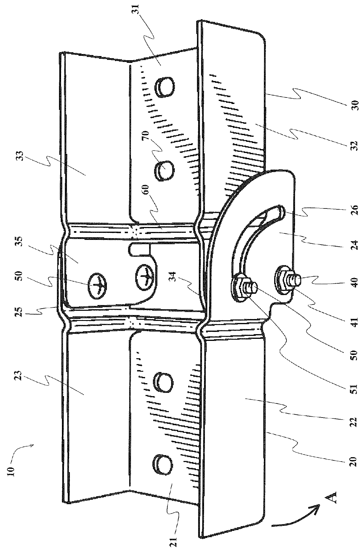
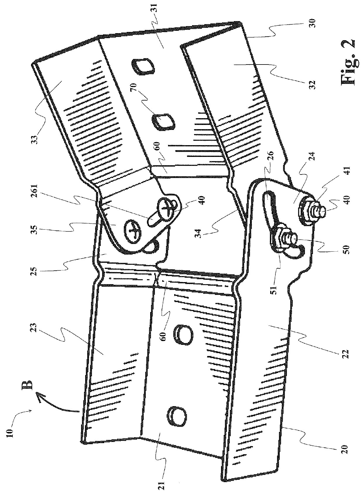
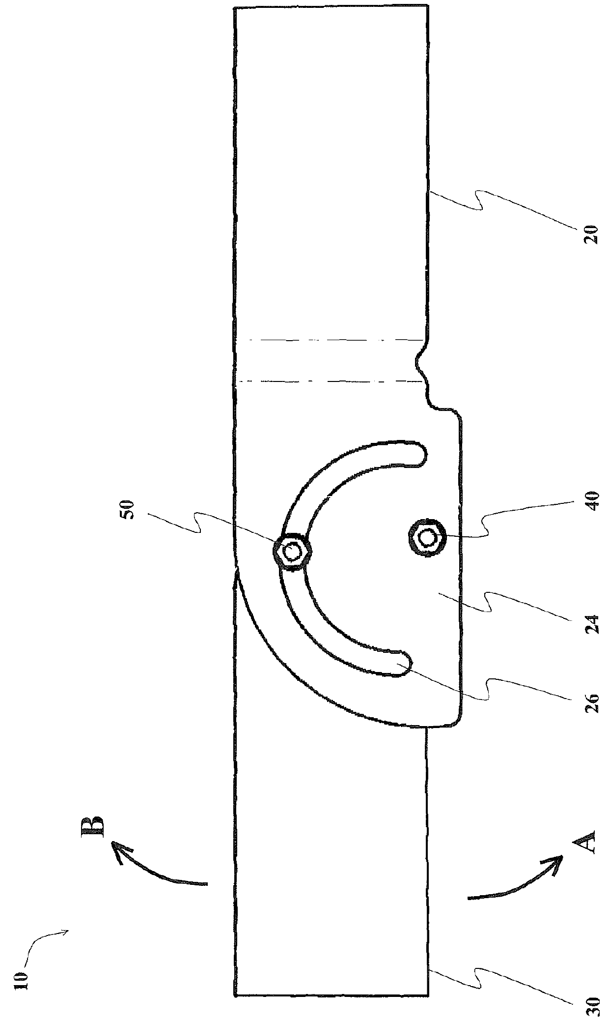
[0040]With reference to FIG. 1, an adjustable cable tray joint 10 includes a first tray receptacle 20 and a second tray receptacle 30. First tray receptacle 20 inc...


PUM


Abstract

An adjustable cable tray joint is provided. The joint has first and second tray receptacles, each having a web and opposing walls. The first tray receptacle may further include joint flanges extending from its walls. The first and second tray receptacles are attached together by pivotal connection, the receptacles defining a rotation relative to each other about the pivotal connection. The joint flanges of the first tray receptacle are disposed proximate to the corresponding walls of the second tray receptacle. The joint includes a locking member extending through a wall of the first tray receptacle and the corresponding wall of the second tray receptacle, the locking member configured to selectively fix and release the rotation between the two tray receptacles.

Description

FIELD OF THE INVENTION[0001]The presently disclosed technology relates to a connection member for cable tray systems. More particularly, the presently disclosed technology is directed to a cable tray joint that is adjustable to provide angular redirection of cable tray runs.BACKGROUND OF THE INVENTION[0002]Cable tray systems are structures that are used to support, fasten, and manage cables, tubes, conduit, and wires. Cable tray systems may be used in industry, power generation facilities, manufacturing plants, and the like, and elsewhere where such purposes exist. The cable trays used in these systems often have a U-shaped or an L-shaped cross-section, with the cables, tubes, conduits, and / or wires carried within the U-shape or L-shape. In many applications, it is required that a completed cable tray system have structural rigidity. In other applications, not only is structural rigidity required, but also the completed system must be such that electrical arcing between connected me...

Claims


Application Information

Patent Timeline
Patent Type & Authority Patents(United States)
IPC IPC(8): F16L3/00
CPCH02G3/0608Y10T403/32073Y10T403/32377
Inventor WHITE, THOMAS C.
Owner JAMES C WHITE CO INC
Why Eureka
Try Eureka