Supercharge Your Innovation With Domain-Expert AI Agents!

Light output control device for laser light source

a control device and laser light source technology, applied in the direction of optical radiation measurement, instrumentation, color signal processing circuit, etc., can solve the problems of rgb semiconductor laser temperature stabilization time difference, and inability to achieve optimal temperature. to achieve the effect of preventing color balance from being los

Inactive Publication Date: 2012-05-01
GK BRIDGE 1
View PDF15 Cites 0 Cited by
  • Summary
  • Abstract
  • Description
  • Claims
  • Application Information

AI Technical Summary

Benefits of technology

The solution ensures that the rising of RGB light outputs match each other, preventing color balance issues by controlling the semiconductor lasers to operate in accordance with the slowest rising time, thereby maintaining accurate color reproduction.

Problems solved by technology

Particularly, it is highly likely that an optimum temperature has not been reached upon start-up, and also when temperature control is performed, it takes time for the temperature to stabilize.
Moreover, there is a possibility that a difference may occur in temperature stabilization time between RGB semiconductor lasers.
Thus, the rising of RGB light outputs do not match one another and there is a possibility that light of colors different than expected may come out and thus it is not preferable as a display backlight.

Method used


Image

  • Light output control device for laser light source
  • Light output control device for laser light source
  • Light output control device for laser light source

Examples


first embodiment

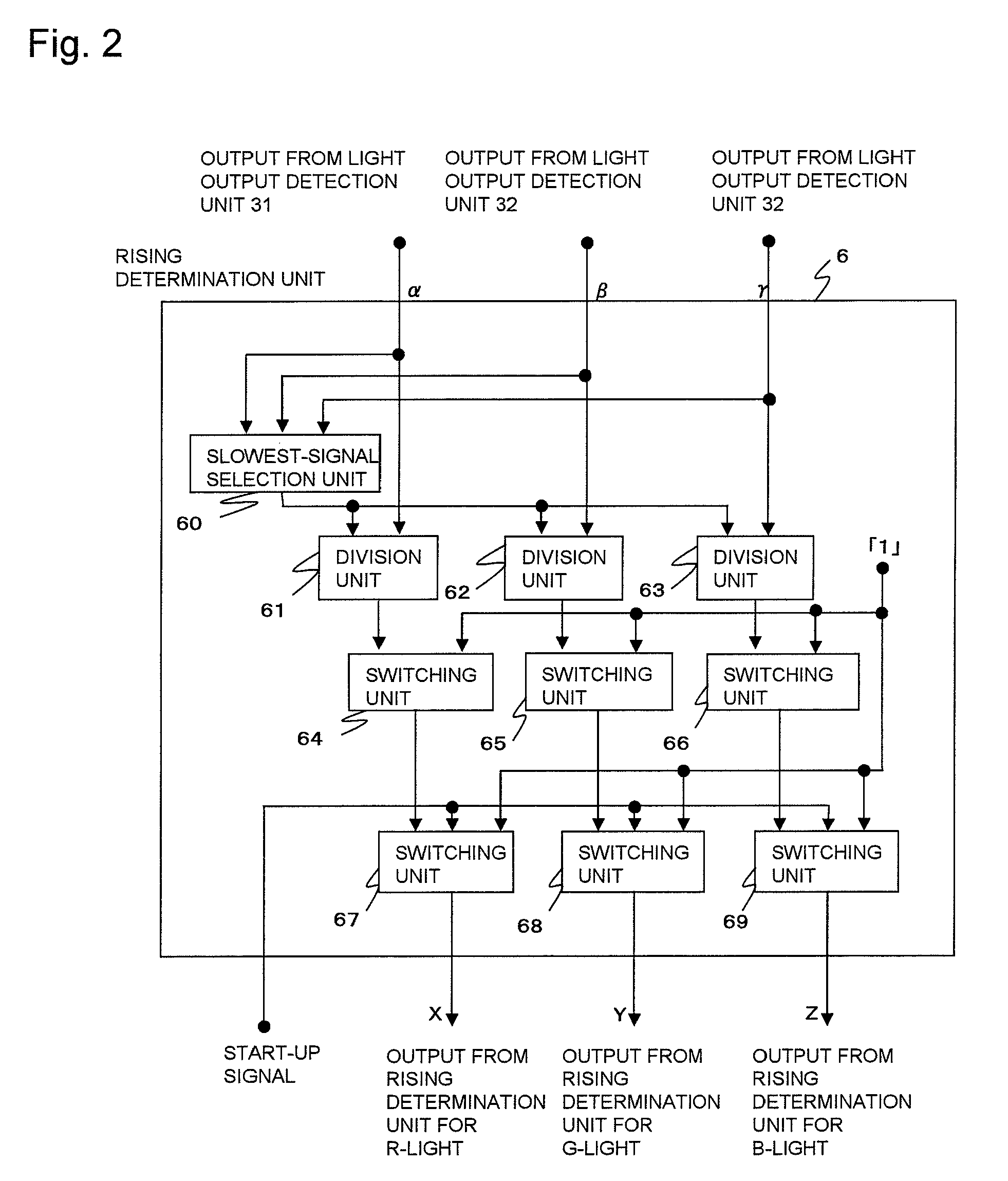
[0024]A configuration of a light output control device for laser light sources according to a first embodiment of the present invention will be described with reference to FIGS. 1, 2, and 3. FIG. 1 is a block diagram showing a configuration of a light output control device for laser light sources according to the first embodiment of the present invention. The light output control device includes, for each of three colors R (red), G (green), and B (blue), three sets of: light output adjustment unit 11, 12, and 13; light output control unit 21, 22, and 23; semiconductor lasers 41, 42, and 43 that output lights of the respective RGB colors; division unit 51, 52, and 53; and light output detection unit 31, 32, and 33. The light output control device also includes rising determination unit 6. The light output adjustment unit 11, 12, and 13 update their respective RGB light output target values. The light output control unit 21, 22, and 23 respectively control light outputs from the semic...


PUM


Abstract

A light output control device for laser light sources for respective RGB colors includes, for each of RGB, three sets, each including: a semiconductor laser for one of the colors; light output detection unit for detecting a light output from the semiconductor laser; light output adjustment unit for updating a light output target value; light output control unit for controlling the semiconductor laser based on the updated light output target value; and division unit for dividing the light output by an output from the light output adjustment unit to obtain a ratio of the rising of the light output, and includes rising determination unit for determining, based on results obtained by the respective division unit, a semiconductor laser with a slowest rising and outputs light output adjustment values for the respective colors. The light output adjustment unit update their respective light output target values based on the light output adjustment values. The light output control unit causes their respective corresponding semiconductor lasers to operate in accordance with a semiconductor laser whose rising time is slowest, based on the updated light output target values to keep RGB color balance upon start-up.

Description

[0001]The present application claims the priority of Japanese Patent Application No. 2007-186921, filed on Jul. 18, 2007 in Japan, and the contents of which are incorporated herein by reference.BACKGROUND OF THE INVENTION[0002]1. Technical Field[0003]The present invention relates to a light output control device for laser light sources used as a backlight of a display.[0004]2. Background Art[0005]In a laser light source device used as a backlight of a display, to reproduce correct colors, the magnitudes of respective RGB light outputs need to have specified values. Upon a normal operation, a light output from a laser light source is detected and fed back to drive unit, whereby the light output is controlled to a specified light output. This is generally called APC control.[0006]FIG. 6 is a block diagram showing a configuration of a conventional light output control device. This light output control device includes, for the respective RGB colors, light output control unit 21, 22, and...

Claims


Application Information

Patent Timeline
Patent Type & Authority Patents(United States)
IPC IPC(8): H05B37/00
CPCH01S5/4025H01S5/0683H01S5/4087
Inventor INOUE, SHUJIKOBAYASHI, TAKAHIROMITANI, HIROSHIONISHI, TOSHIKINISHIKOJI, YUICHI
Owner GK BRIDGE 1
Features
  • R&D
  • Intellectual Property
  • Life Sciences
  • Materials
  • Tech Scout
  • Unparalleled Data Quality
  • Higher Quality Content
  • 60% Fewer Hallucinations
Learn More