Angular position sensor

a position sensor and angular technology, applied in the field of angular position sensors, can solve the problems of high heat damage to sensors, disadvantages of braking systems, and relatively extreme conditions for components of braking systems, and achieve the effect of high accuracy of position data

Active Publication Date: 2012-05-01
HYDRO AIRE AEROSPACE CORP
View PDF40 Cites 15 Cited by
  • Summary
  • Abstract
  • Description
  • Claims
  • Application Information

AI Technical Summary

Benefits of technology

[0008]The present invention overcomes the disadvantages inherent in previously known angular position sensors to provide for highly accurate position data in extremely hostile environments. The device is robust and does not require direct coupling between rotating components. As such it is ideally suited for generating wheel speed data in aircraft applications.

Problems solved by technology

The components of braking systems may be subjected to fairly extreme conditions, including high temperatures, vibration and shock loads, as well as water and dirt contamination.
While such a configuration allows for the use of a reliable and accurate inducer to generate the required wheel speed data, the weight, bulk and complexity of such a system is disadvantageous.
The use of Hall sensors has also previously been proposed, but the configurations that had been considered rendered the sensors particularly susceptible to heat damage and required an inordinate number of magnets and sensors in order to achieve the desired accuracy.

Method used


Image

  • Angular position sensor
  • Angular position sensor

Examples


Embodiment Construction

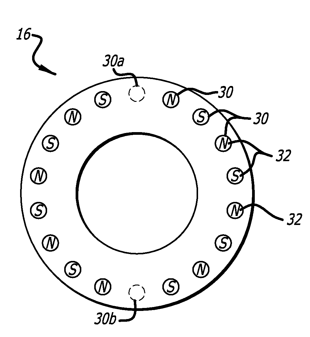
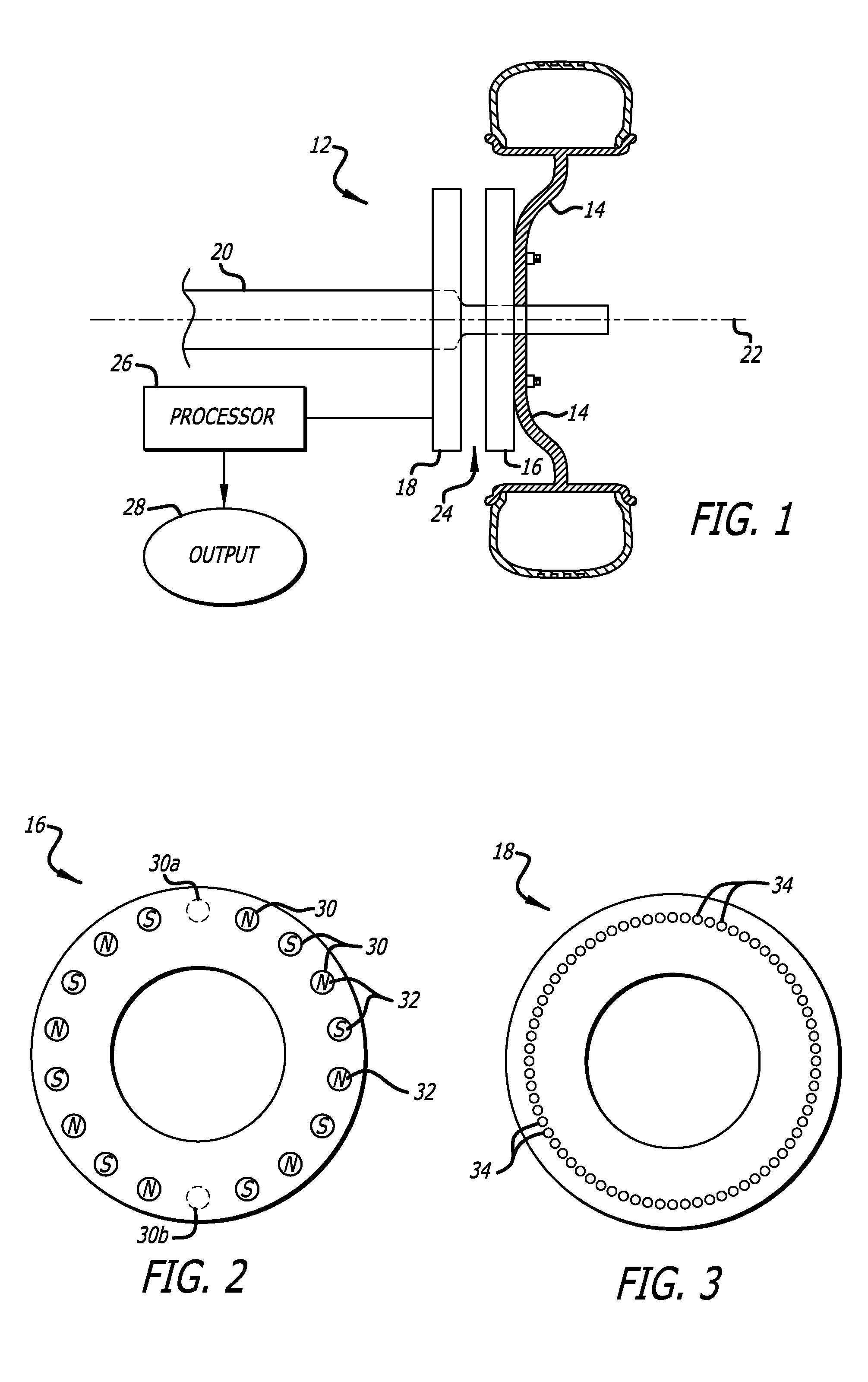
[0014]The present invention is directed to an angular position sensor which may readily be adapted to, a wheel, for example, and used to control an antilock or antiskid braking system for such wheel. The system 12 is very generally and schematically illustrated in FIG. 1. wherein a wheel 14 has a target plate 16 associated with it so as to rotate in unison, while a stationary sensor board 18 is affixed to a non-rotating axle 20 or other support element. In a presently preferred embodiment, a circular target plate and circular sensor board are centered about a common axis 22 and are separated by a small air gap 24. One or more processors 26 convert data generated by the sensor board to a useable output such as angular position, rate of rotation or wheel speed.

[0015]In the preferred embodiment schematically illustrated in FIG. 2, the target plate 16 has a total of eighteen magnet positions 30 that are equidistantly distributed about its periphery in 20 degree increments wherein sixtee...


PUM


Abstract

An angular position sensor and method that relies on a stationary circular array of Hall sensors and a rotatable circular array of magnets arranged about a common axis. A periodic and simultaneous reading of all of the Hall sensor outputs is used to determine angular velocity.

Description

CROSS-REFERENCES TO RELATED APPLICATIONS[0001]This application claims priority from U.S. Provisional Application No. 60 / 933,340, filed 6 Jun. 2007, incorporated by reference in its entirety.BACKGROUND OF THE INVENTION[0002]1. Field of the Invention[0003]The present invention is generally directed to an angular position sensor and more particularly pertains to a sensor that is capable of extremely accurate angular position determinations in very hostile environments.[0004]2. Description of the Related Art[0005]There are many applications in which the accurate determination of the angular position of one component relative to another is critical. Moreover, accurate determination of angular position allows for the accurate calculation of angular speed and acceleration which is vital, for example, for the effective operation of high performance anti-lock or anti-skid braking systems. The components of braking systems may be subjected to fairly extreme conditions, including high temperat...

Claims


Application Information

Patent Timeline
Patent Type & Authority Patents(United States)
IPC IPC(8): G01B7/30
CPCB60T8/171B60T8/329G01D5/145G01P3/487G01R33/0094
Inventor ZAK, MARK
Owner HYDRO AIRE AEROSPACE CORP
Why Eureka
Try Eureka