
Hearing aid having two receivers each amplifying a different frequency range

a technology of hearing aids and receivers, applied in the field of hearing aids, can solve the problems of limited bandwidth enhancement in general, particularly difficult to apply to behind-the-ear hearing aids,

Active Publication Date: 2012-05-01
SONION NEDERLAND
View PDF9 Cites 85 Cited by
  • Summary
  • Abstract
  • Description
  • Claims
  • Application Information

AI Technical Summary

Benefits of technology

The patent describes a hearing aid system that includes a housing, two receivers, and a tube. The first receiver amplifies low-frequency sounds, while the second receiver amplifies high-frequency sounds. The tube is connected to the output of the first receiver. The system can also include a sound path that connects the output of the first receiver to the second receiver. The technical effect of this design is that it allows for improved amplification of both low- and high-frequency sounds, resulting in a more natural and accurate hearing experience for users.

Problems solved by technology

There is a trend to increase the bandwidth of the hearing aid, but this trend is particularly difficult to apply to behind-the-ear (BTE) hearing aids because the long sound tubing inserted between the receiver sound port and the sound outlet of the ear mold suppresses the high frequencies.
Bandwidth enhancement in general has been limited by the available processing power of the DSPs within the hearing aid, in which the audio sampling rates typically have been limited to a sample rate of about 16 kHz with a resulting audio bandwidth slightly below 8 kHz.

Method used


Image

  • Hearing aid having two receivers each amplifying a different frequency range
  • Hearing aid having two receivers each amplifying a different frequency range
  • Hearing aid having two receivers each amplifying a different frequency range

Examples


Embodiment Construction

[0025]There are at least three considerations in optimizing hearing aids in general: (1) its size should be as small as possible; (2) its power consumption should be as small as possible; and (3) its maximum sound pressure output should, as a general rule, be as high as possible. Another consideration is also becoming very important: (4) bandwidth should be as high as possible. The present invention achieves optimization of all four of the foregoing considerations by providing two receivers, each of which is separately optimized for different frequency ranges.

[0026]Though the addition of a second receiver may appear at first blush to increase overall size, in fact, each receiver can be optimized to a smaller size and can be distributed in the hearing aid in different areas or orientations, thereby saving overall space. By providing a separate receiver specially optimized at low frequencies, the resonance frequency is lowered, substantially increasing low frequency efficiency when co...


PUM


Abstract

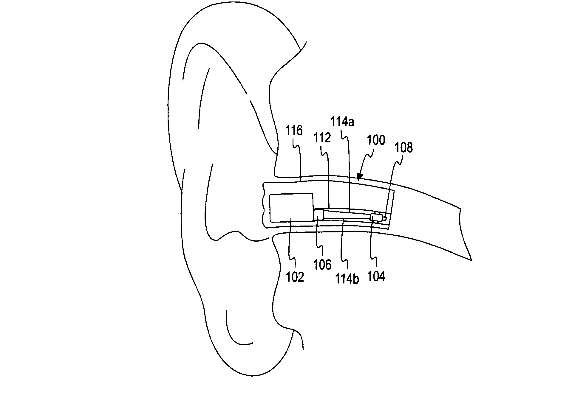
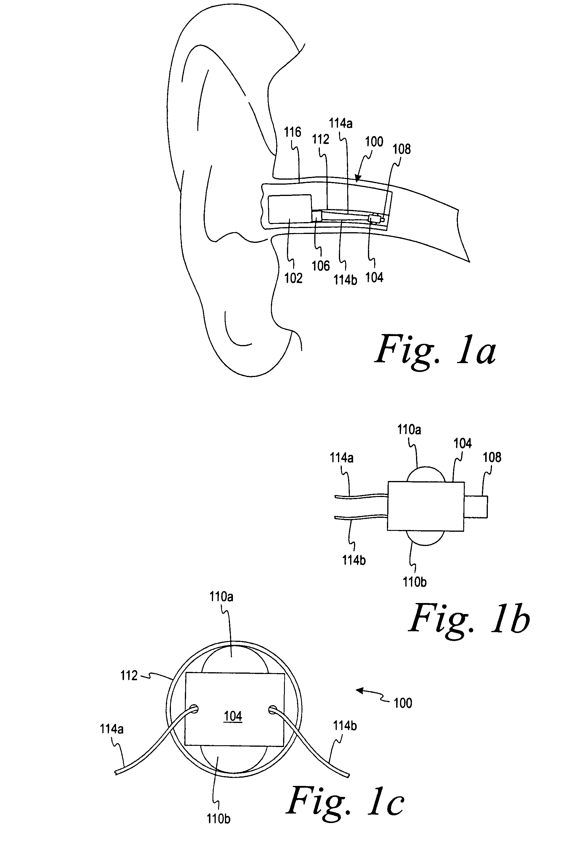
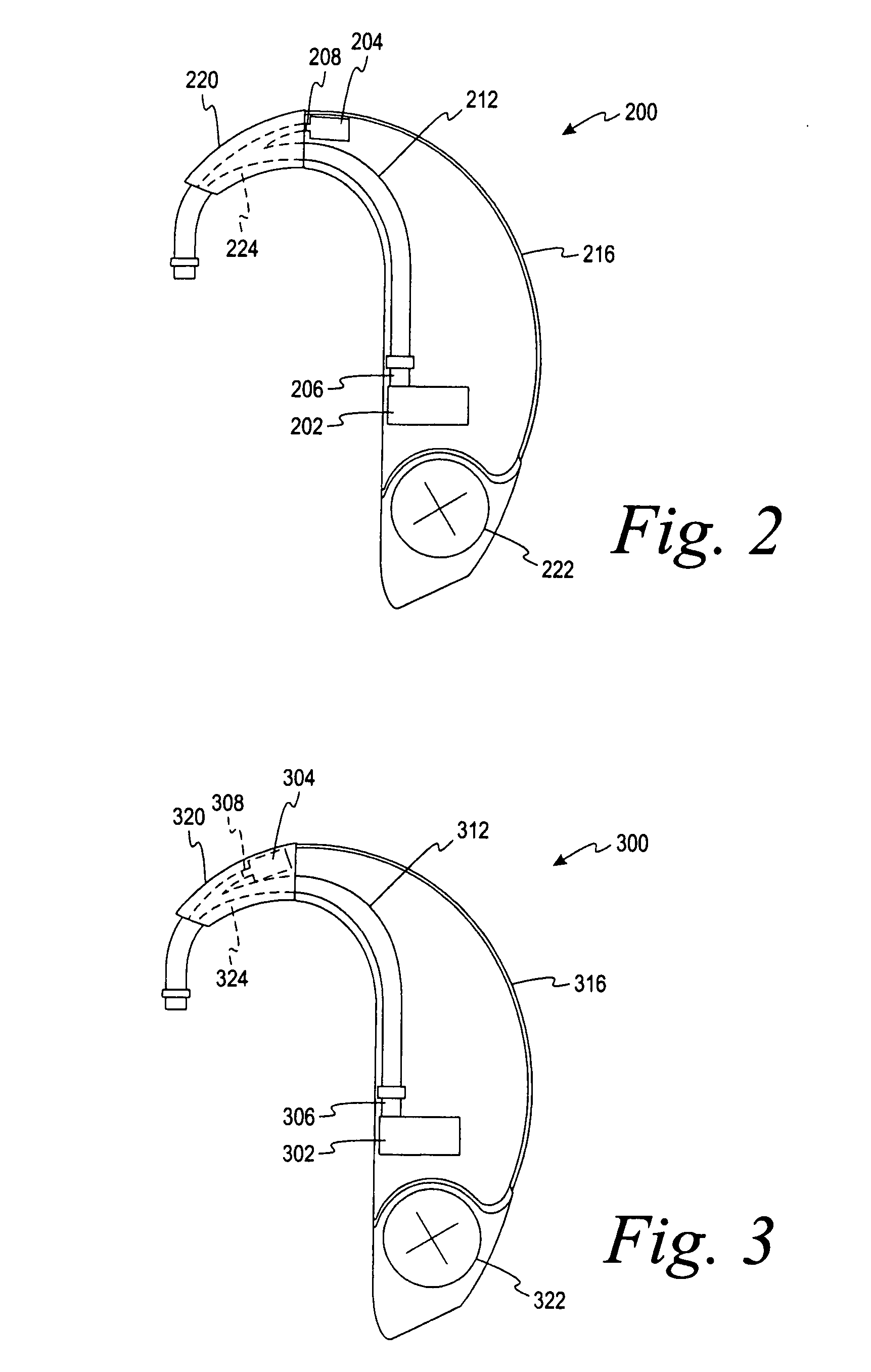
A hearing aid having two physically separate receivers, one for outputting low frequency (LF) acoustic sounds and another for outputting high frequency (HF) acoustic sounds. The LF receiver's output port is connected to a tube in which the HF receiver is inserted. The LF acoustic sounds either flow around the HF receiver, which include standoffs to space the HF receiver away from the inner tube wall, or through a channel in the HF receiver. At the output of the HF receiver, the LF and HF acoustic sounds are combined to form an acoustic signal that is transmitted to the ear canal. The LF receiver can be optimized for compliance, distortion, resonance frequency, and output. Its orientation is selected for reducing the overall size of the hearing aid. The HF receiver is smaller and placed far away from any microphone(s), reducing feedback effects, and may have a cylindrical or rectangular shape.

Description

CROSS REFERENCE TO RELATED APPLICATION[0001]This application claims the benefit of U.S. Provisional Application No. 60 / 814,858, filed Jun. 19, 2006, titled “Hearing Aid Having Two Receivers Each Amplifying a Different Frequency Range,” which is hereby incorporated by reference in its entirety.FIELD OF THE INVENTION[0002]This invention relates to hearing aids, and, more particularly, to a hearing aid having two receivers each amplifying a different frequency range.BACKGROUND OF THE INVENTION[0003]Today's hearing aids include only one receiver that, together with the hearing-aid acoustics (tubing, wax protection devices, etc.) connected to it, has a resonance frequency that lies between 2 kHz and 3.5 kHz. There are two primary reasons for this limitation. First, the un-occluded ear has significant gain in this frequency range, which is removed by blocking the open ear canal with an closed-fitting earmold. Second, in order to achieve an acceptable output and efficiency at both low and ...

Claims


Application Information

Patent Timeline
Patent Type & Authority Patents(United States)
IPC IPC(8): H04R25/00
CPCH04R25/48
Inventor HALTEREN, AART ZEGER VAN
Owner SONION NEDERLAND
Learn More