Transit system vehicle guideway constructed from modular elements and using magnetic levitation for suspension and propulsion vehicles

a transit system and vehicle guideway technology, applied in the field of networked guideway transit systems, can solve the problems of unavoidable wear accompanying wheels rolling on tracks, add significantly to the complexity and potential failure points of prt systems, and achieve the effect of reducing the static weight, cost and physical size of the guideway structure, and facilitating the installation of the vehicl

Active Publication Date: 2012-05-08
SKYTRAN
View PDF14 Cites 33 Cited by
  • Summary
  • Abstract
  • Description
  • Claims
  • Application Information

AI Technical Summary

Benefits of technology

[0009]The networked guideway transit system uses materials and methods of constructing guideway elements. The materials and methods are designed to reduce the static weight, cost and physical size of the guideway structure. Installation cost is also significantly reduced by the modular nature of the guideway components, which can be manufactured in a controlled factory environment using mass production methods. As a result, the supporting structure of the guideway can be quickly erected and the modular blocks inserted with simple equipment. In addition, complex alignment procedures are not required.
[0010]In accordance with some embodiments, an electrodynamic repulsion apparatus used in the networked guideway transit system that utilizes permanent magnet levitation and electrodynamic repulsion is provided. The electrodynamic repulsion apparatus provides passive centering forces for a vehicle bogie that is moving. The electrodynamic repulsion apparatus comprises a pair of coil arrays, each of which includes a plurality of groups of coil components. Each pair of coil arrays includes three electrical phases of the coil components wherein the coil components within each electrical phase are linked together in series. In this manner, the number of turns in each coil can be reduced, thus reducing manufacturing cost. The pair of coil arrays is configured to be individually switched on and off regardless of the operation of adjacent electrodynamic repulsion components, thus enhancing electrical operating efficiency.

Problems solved by technology

However there are technical barriers to the design and implementation of effective PRT systems or guideways for the PRT systems.
One of the technical aspects that continue to pose a significant barrier to implement PRT systems may be the use of wheels as the primary method of suspending vehicles.
Although wheels are a familiar and common technology, their associated bearing surfaces and the mechanical devices required to make wheels navigate a track network add significantly to the complexity and potential failure points of a PRT system.
In addition, the unavoidable wear accompanying wheels rolling on tracks becomes a significant maintenance problem when a typical system might utilize thousands, or tens of thousands of vehicles.
Further, the use of wheels imposes a speed limitation on the vehicles.
But any effort to build a larger network or to link smaller networks together across realistic travel distances will face the wheel related problems.
And keeping the maximum speeds low means the transit times for the greater distances will be unacceptably long for most patrons.
In other words, expanding a local circulator or linking two local circulator PRT systems is not practical with vehicle using small wheels.
However, building a larger wheel-based PRT system may be prohibitively expensive.
Current PRT systems lack an economical, reliable and lightweight means to carry vehicles in slower speed, tight systems and faster, longer distance systems.
Specifically, the installation cost and intrusiveness of a guideway are the most critically limiting factors for a comprehensive PRT system installation, so great emphasis has been placed on reduction of both of these factors.
A major part of the cost of a transit system is maintenance.

Method used


Image

  • Transit system vehicle guideway constructed from modular elements and using magnetic levitation for suspension and propulsion vehicles
  • Transit system vehicle guideway constructed from modular elements and using magnetic levitation for suspension and propulsion vehicles
  • Transit system vehicle guideway constructed from modular elements and using magnetic levitation for suspension and propulsion vehicles

Examples


Embodiment Construction

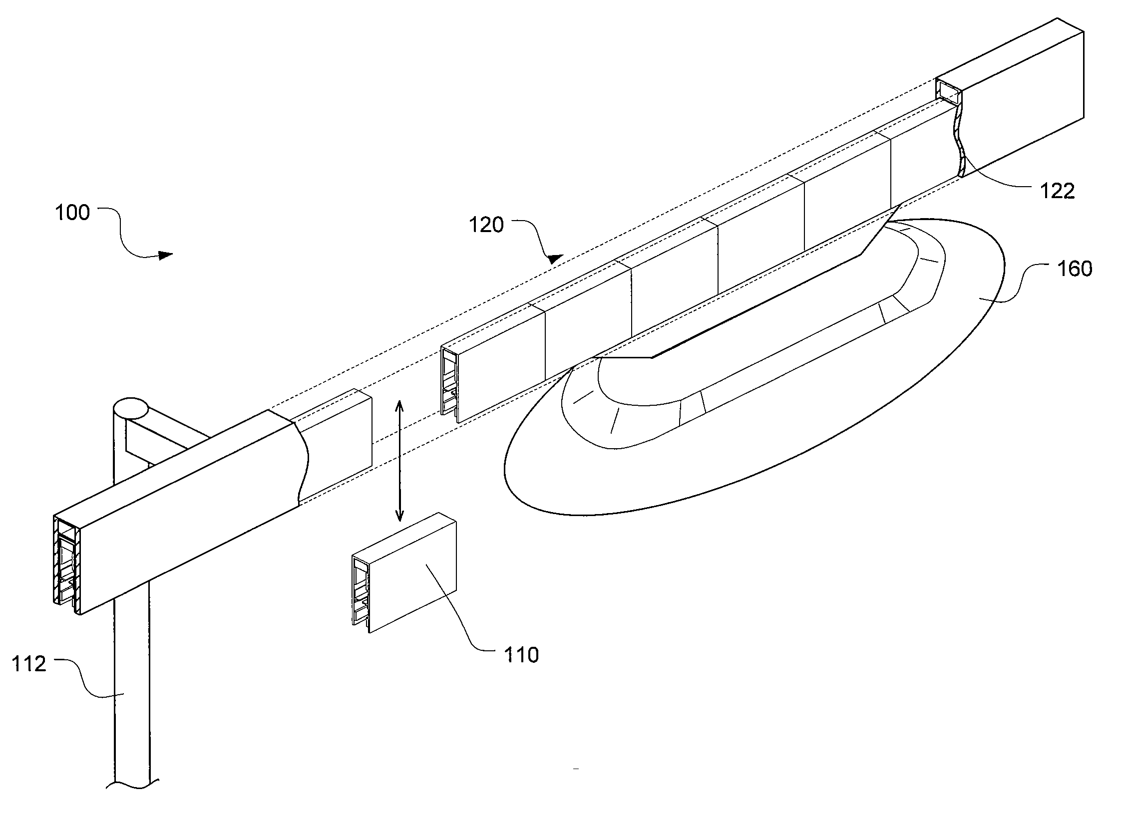
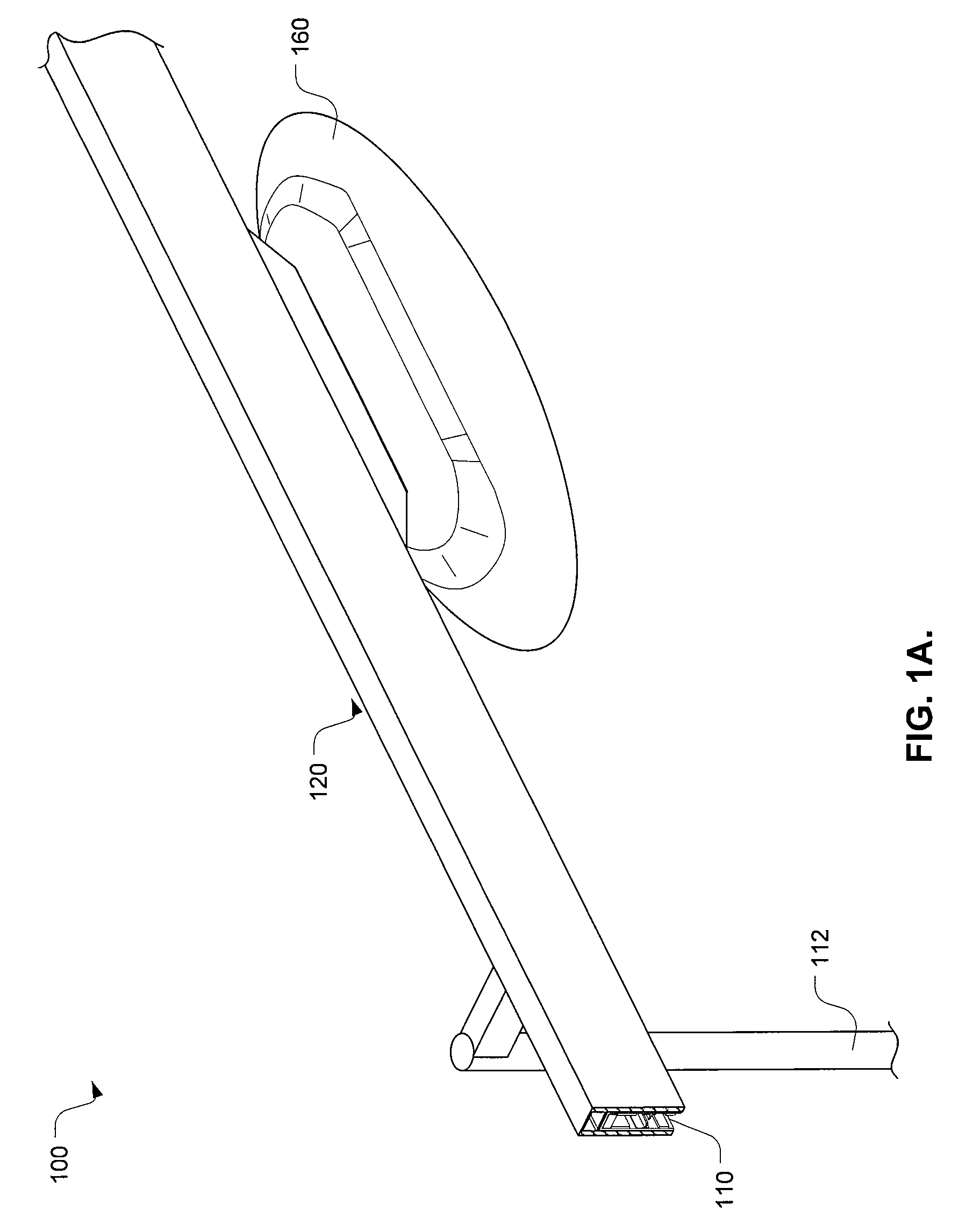
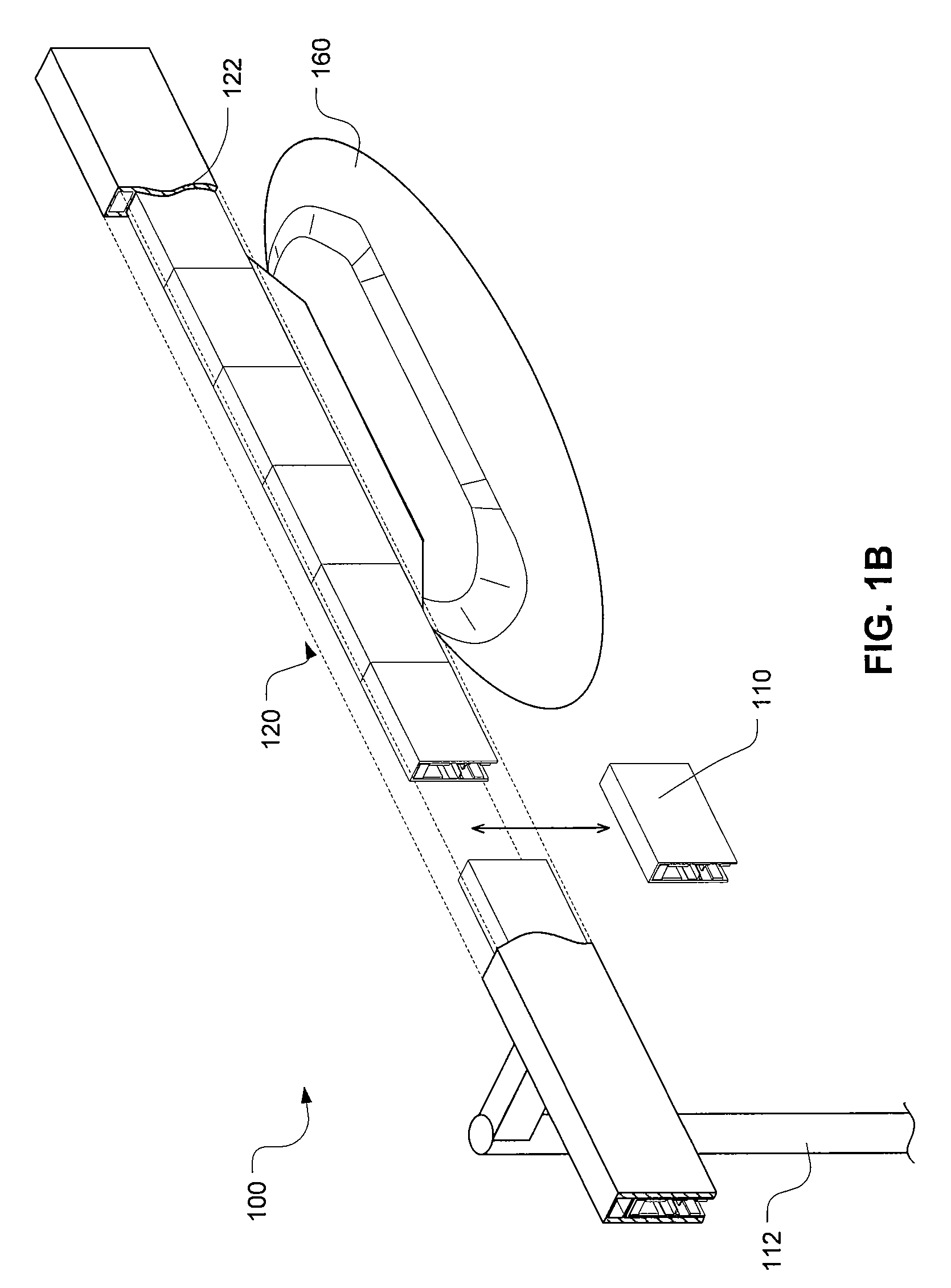
[0024]A method and system to integrate magnetic levitation technologies within a networked guideway transit system is provided. A method and system is also provided for modeling the networked guideway transit system as a form of packet switched data transfer network using a globally unique identifier. The magnetic levitation is used to replace wheels as the primary means of vehicle suspension and thus the automated transit systems (e.g., PRT system) can be made commercially and economically feasible. More specifically, a method and system use permanent magnet repulsion with induction-based repulsion within the networked guideway transport system, which can levitate passively with motion.

[0025]Generally described, the networked guideway transit system combines permanent magnet levitation with electrodynamic stabilization and linear motor propulsion. That is, the networked guideway transit system uses the permanent magnets to provide primary lift and uses electrodynamic repulsion to c...


PUM


Abstract

The networked guideway transit system uses materials and methods of constructing guideway elements. The materials and methods are designed to reduce the static weight, cost and physical size of the guideway structure. Installation cost is also significantly reduced by the modular nature of the guideway components, which can be manufactured in a controlled factory environment using mass production methods. As a result, the supporting structure of the guideway can be quickly erected and the modular blocks inserted with simple equipment. In addition, complex alignment procedures are not required. In particular, the guideway component includes motor coils having the shapes and configurations that facilitate the easy insertion of the guideway component without the need for interleaving coils in adjacent guideway components and without creating dead spots in the magnetic fields between guideway components.

Description

CROSS-REFERENCES TO RELATED APPLICATIONS[0001]The present application claims benefit to U.S. provisional patent application No. 60 / 870,886, filed Dec. 20, 2006, the complete disclosure of which is incorporated herein by reference.BACKGROUND[0002]The present invention is directed to transportation or transit systems, and more specifically, to networked guideway transit systems designed to enable the movement of large numbers of passengers or parcels in a flexible manner.[0003]Guideway-based transportation systems have been used to transport people or goods. One example is a “Personal Rapid Transit” (PRT) system. In the PRT system, each vehicle carries just one party or small group (or payload) from their origin directly to their destination, starting at a time determined by the party's arrival at its origin. Vehicles are typically piloted by computer and move non-stop along guideways with diverging and merging paths.[0004]The PRT system can offer great advantages over other transport...

Claims


Application Information

Patent Timeline
Patent Type & Authority Patents(United States)
IPC IPC(8): B60L13/04
CPCB60L13/04B60L2200/26Y02P90/60
Inventor WAMBLE, III, JOHN LEEPERKINS, CHRISTOPHERCOLE, JOHN V.FOSTER, CLARK
Owner SKYTRAN
Why Eureka
Try Eureka