Photovoltaic mounting system with locking connectors, adjustable rail height and hinge lock

a photovoltaic and mounting system technology, applied in the direction of heat collector mounting/support, rod connection, lighting and heating apparatus, etc., can solve the problems of large skill and precision in the installation process, and the conventional method of installation consumes many man-hours of installation labor, and achieves cost-effective effects

Inactive Publication Date: 2012-05-15
POWERMOUNT SYST +1
View PDF20 Cites 69 Cited by
  • Summary
  • Abstract
  • Description
  • Claims
  • Application Information

AI Technical Summary

Benefits of technology

[0012]The apparatus provides quick and secure connections that, during the process of connecting the mounting grid components, allow the installer to expedite the assembly of the PV panel mounting structure. The cam connector allows the installer the flexibility to position and reposition the grid as needed to achieve the final mounting configuration quickly. When the frame is determined to be in the proper position, the cam connector is easily turned to lock it in the final tensioned position. This and other unique design features of the cam-actuated connector and equalized clamping action rail member system are estimated to reduce installation time by up to 60 percent over conventional practices. The invention also provides a self-locking feature that, while being tightened into its working condition, allows the split inner barrel of the cam actuator to tighten in a manner that forces the cam surfaces into opposite direction, thereby firmly locking the device in position.
[0013]The time saving aspects of the invention are many. Primary among them is the ability for individual connectors to be attached in a series of chained connectors using a common tightening device such as a tensioning jack or cam arm. In addition, the ability of the cam connector to be removed, repositioned and reconnected many times over the life of the photovoltaic system uniquely suits the system for future PV enhancements. With advancements in photovoltaic efficiency, this capability allows panels to be replaced with new panels that may or may not be of the same physical size. The cam-actuated fasteners are easily loosened, repositioned and retightened in accordance with the requirements of the new photovoltaic array. There is no limit to the number of this type of system change.
[0018]A departure from the above-mentioned mounting rail is an alternative rail mounting extrusion designed to create a removable hinged connection between the rail and the mating extrusion that is affixed to, or extruded into, the PV module frame. The male / female connection allows the PV module to be inserted into the mounting rail track in a near perpendicular position allowing the wire leads affixed to the backs of each PV module to be interconnected. This then allows the modules to be lowered into their working position. Once the PV modules are lowered into their working position they are locked into position with a fastener such as a screw or another extrusion that slides into the mounting rail for positively locking the entire row of PV modules in position.
[0020]The described fastening mounting rails and clamping PV panels forms a mounting system that when used as a complete system allows for a cost-effective and labor-reducing installation package.

Problems solved by technology

The conventional methods of installation generally consume many man-hours of installation labor and must be placed in precise locations to accommodate the specific PV panels supplied for the installation.
This is a project that requires significant skill and precision.

Method used


Image

  • Photovoltaic mounting system with locking connectors, adjustable rail height and hinge lock
  • Photovoltaic mounting system with locking connectors, adjustable rail height and hinge lock
  • Photovoltaic mounting system with locking connectors, adjustable rail height and hinge lock

Examples


Embodiment Construction

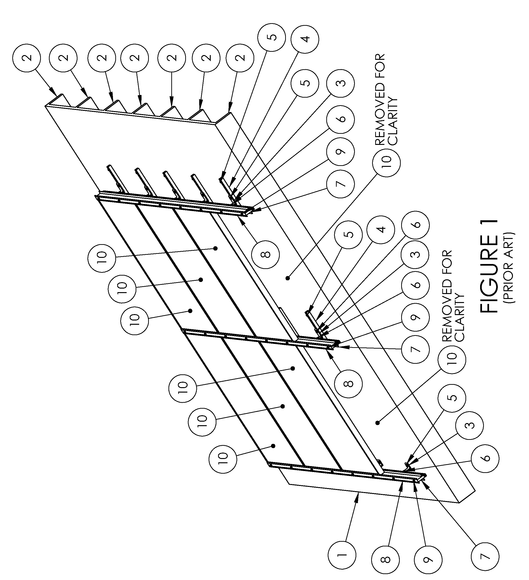
[0058]Referring to FIG. 1, a portion of a conventional residential roof structure 1 is shown, and presents a common mounting medium for which the present invention is particularly suited. The portion shown in FIG. 1 is typical of a residential roof structure, having support beams over which one or more weatherproof sheets is attached, such as plywood and shingles. Of course, the roof structure 1 is merely one example of a structure to which the present invention can be mounted, as will be understood by the person having ordinary skill in the design and installation of photovoltaic electrical systems. The residential roof structure 1 is described herein, but it will be understood by the person of ordinary skill that other structures can be substituted for the structure 1, including without limitation a commercial, institutional or agricultural roof structure, a planar structure built specifically to support a PV array, a wall or ground-mounted area, or any other stable, fixed structu...


PUM

PropertyMeasurementUnit
anglesaaaaaaaaaa
tensionaaaaaaaaaa
flexibilityaaaaaaaaaa

Abstract

A cam-actuated connection device joins rail mounting members of a photovoltaic panel array. The connection device slides within channels of mounting members until the members are in a properly positioned grid. When in position, the connection device is rotated to lock the mounting members in a rigid grid network. The connecting device can be subsequently loosened, repositioned and locked into position. The rail-mounting members create a grid for installation of multiple PV panels. The mounting rail allows the unit to remain relatively compact in nature but still covers a wide range of PV panel thicknesses. The rail system has a hinged connection with the mounting rail that allows an installer to assemble the module in a near perpendicular fashion to the mounting rail, make the required electrical connections and then lower the PV module into its working position. The unit is then locked into its working position.

Description

CROSS-REFERENCES TO RELATED APPLICATIONS[0001]This application claims the benefit of U.S. Provisional Application No. 61 / 054,296 filed May 19, 2008, and U.S. Provisional Application No. 61 / 090,055 filed Aug. 19, 2008, both of which are incorporated herein by reference.STATEMENT REGARDING FEDERALLY-SPONSORED RESEARCH AND DEVELOPMENT[0002](Not Applicable)REFERENCE TO AN APPENDIX[0003](Not Applicable)BACKGROUND OF THE INVENTION[0004]1. Field of the Invention[0005]This invention relates generally to the mounting of photovoltaic panels on rooftops and other structures, and more particularly to hardware to facilitate the mounting of the panels.[0006]2. Description of the Related Art[0007]Photovoltaic (herein, “PV”) mounting grids are commonly used to mount PV panel arrays to building structures, ground mounted systems and a large variety of alternate configurations. In one common configuration, a rail and a cleat are mounted, for example to a rooftop of a home, and the panel arrays are mo...

Claims


Application Information

Patent Timeline
Patent Type & Authority Patents(United States)
IPC IPC(8): E04D13/18
CPCF16B2/185F16B5/0635F16B5/0685F16B7/0493F16B7/182F24J2/5205F24J2/5207F24J2/5211F24J2/5254F24J2/5258F24J2/526F24J2/5264H02S20/00H02S20/23F16B5/0032Y10T24/44573F24J2002/4665F24J2002/4669F24J2002/5226Y02B10/12Y02E10/47Y02E10/50Y10T29/49948Y10T403/32426F24S25/20F24S25/33F24S25/35F24S25/632F24S25/636F24S25/65F24S25/70F24S2025/6004F24S2025/6006F24S2025/807H02S20/30Y02B10/10
Inventor ABBOTT, RONALD E.KENT, PERRY L.ABBOTT, RYAN D.
Owner POWERMOUNT SYST
Why Eureka
Try Eureka