Differential switch with off-state isolation enhancement

a differential switch and off-state isolation technology, applied in electronic switching, pulse technique, transistors, etc., can solve the problem of signal leakage through series switching devices degrading off-state isolation, and achieve the effect of reducing off-state leakage curren

Active Publication Date: 2012-05-15
BAE SYST INFORMATION & ELECTRONICS SYST INTERGRATION INC
View PDF11 Cites 4 Cited by
  • Summary
  • Abstract
  • Description
  • Claims
  • Application Information

AI Technical Summary

Benefits of technology

[0007]One embodiment of the present invention provides a method for reducing off-state leakage current in a differential switching device. The method includes receiving a differential input signal at a differential input of each of a primary switch and a dummy switch. In an enabled-state of the device, the method further includes passing the differential input signal to a differential output of the primary switch. In a disabled-state of the device, the method further includes canceling off-state leakage current at the differential output of the primary switch, by virtue of the dummy switch having its differential output reverse-coupled to the differential output of the primary switch. The method may include preventing the dummy switch from passing signals other than off-state leakage signals. In one such particular case, preventing the dummy switch from passing signals other than off-state leakage signals is achieved using a current source that is set to zero and operatively coupled to the dummy switch. In another such case, preventing the dummy switch from passing signals other than off-state leakage signals is achieved by disabling the dummy switch during on-state functioning of the primary switch.

Problems solved by technology

In any such cases, a common problem associated with the switch is leakage.
In particular, signal leakage though the series switching device degrades off-state isolation (i.e., when the switch is disabled, it still passes the output signal being applied at the inputs), especially at high frequencies.

Method used


Image

  • Differential switch with off-state isolation enhancement
  • Differential switch with off-state isolation enhancement
  • Differential switch with off-state isolation enhancement

Examples


Embodiment Construction

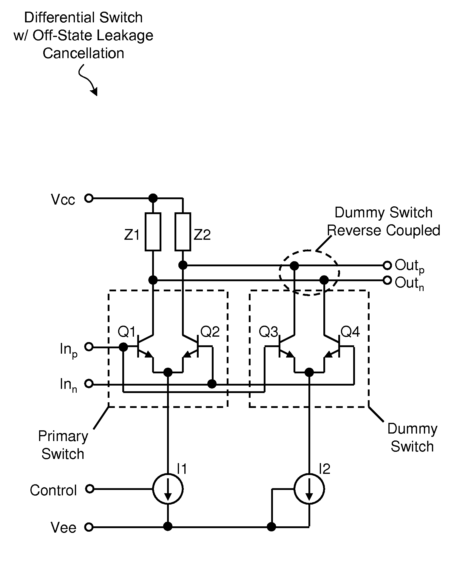
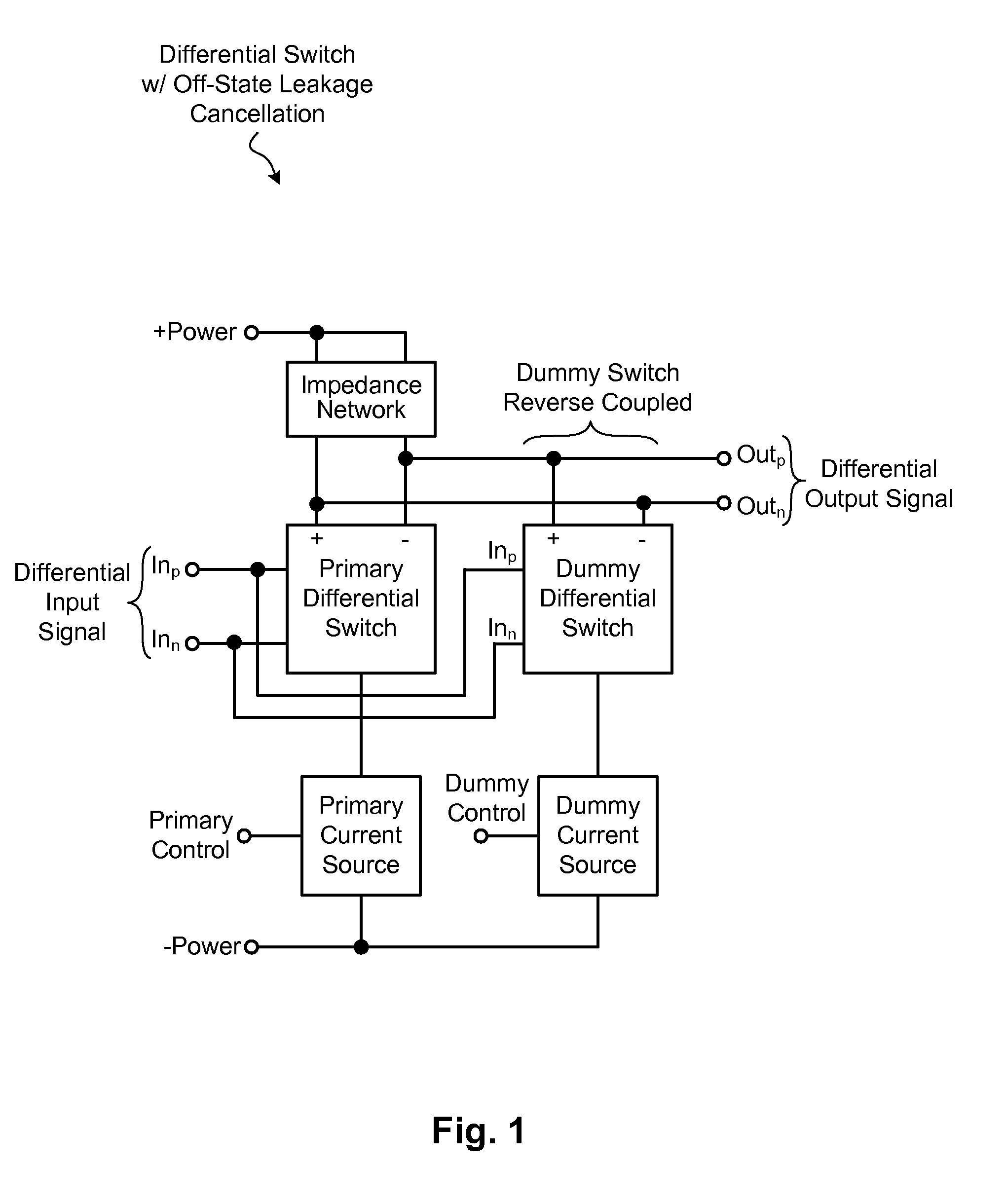
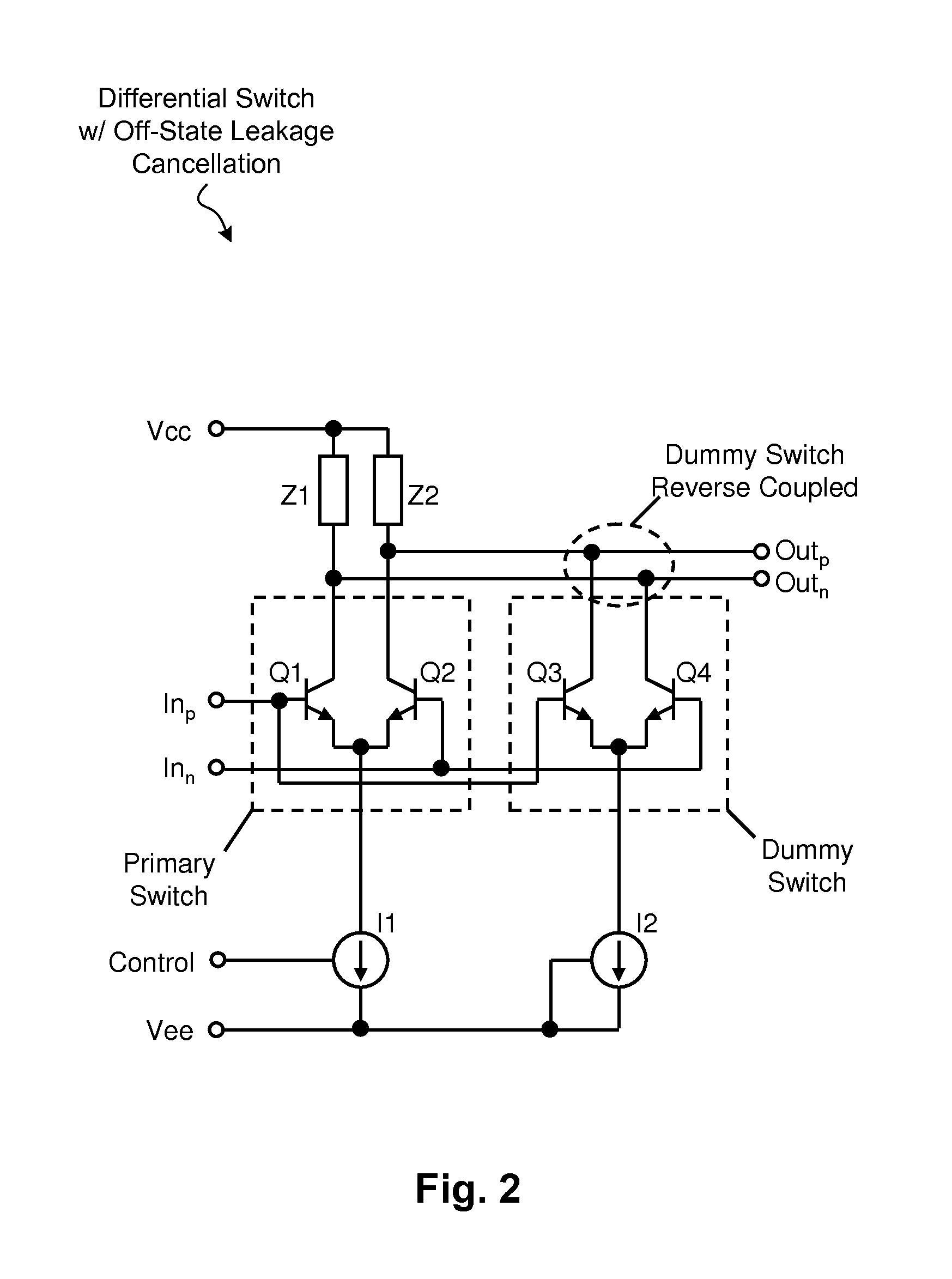
[0014]A differential switching device is disclosed that eliminates or otherwise significantly reduces switch leakage during the switch disabled-state. The switching technique can be implemented in any number of applications, including integrated system-on-chip configurations as well as printed circuit boards configured with various discrete components including differential switches. The frequency range of the switch (e.g., RF, microwave, etc) will depend on the particular application at hand, as will be appreciated in light of this disclosure.

[0015]General Overview

[0016]A differential switch is commonly implemented using a differential pair of transistors, which have their emitters coupled together to a current source. The differential input is provided to the bases of the transistor pair, and the differential output is taken at the corresponding collectors. When the differential switch is enabled (current source is enabled), the differential pair inverts the signal applied to the ...


PUM


Abstract

Techniques are disclosed for reducing off-state leakage current in a differential switching device. The techniques can be embodied, for example, in a method that includes receiving a differential input signal at a differential input of each of a primary switch and a dummy switch. In an enabled-state of the device, the method further includes passing the differential input signal to a differential output of the primary switch. In a disabled-state of the device, the method further includes canceling off-state leakage current at the differential output of the primary switch, by virtue of the dummy switch having its differential output reverse-coupled to the differential output of the primary switch. The method may further include preventing the dummy switch from passing signals other than off-state leakage signals. The techniques can be embodied, for instance, in a switching device.

Description

STATEMENT OF GOVERNMENT INTEREST[0001]The invention was made with United States Government support under contract W15P7T-06-C-P635 awarded by the Army, and the United States Government may have certain rights in this invention.FIELD OF THE INVENTION[0002]The invention relates to electronic switches, and more particularly, to techniques for reducing switch leakage during the disabled-state of differential switches.BACKGROUND OF THE INVENTION[0003]A differential switch is commonly implemented using a differential pair of transistors, which have their emitters coupled together to a current source. The differential input to the switch is provided to the bases of the transistor pair, and the differential output is taken at the corresponding collectors. When the differential switch is enabled (current source is enabled), the differential pair inverts the signal applied to the bases, such that a positive going base signal causes a negative going collector signal (and vice versa, where a ne...

Claims


Application Information

Patent Timeline
Patent Type & Authority Patents(United States)
IPC IPC(8): H03K17/16H03K17/60
CPCH03K19/001
Inventor FLEWELLING, GREGORY M.JANSEN, DOUGLAS S.
Owner BAE SYST INFORMATION & ELECTRONICS SYST INTERGRATION INC
Why Eureka
Try Eureka