Composite antenna
a technology of composite antennas and antennas, applied in the structure of resonant antennas, instruments, radiating elements, etc., can solve the problems of short distance communication and unstable communication, and achieve the effects of improving radiation characteristics and communication performance, stabilizing communication performance, and high coupling between the two antennas
- Summary
- Abstract
- Description
- Claims
- Application Information
AI Technical Summary
Benefits of technology
Problems solved by technology
Method used
Image
Examples
first preferred embodiment
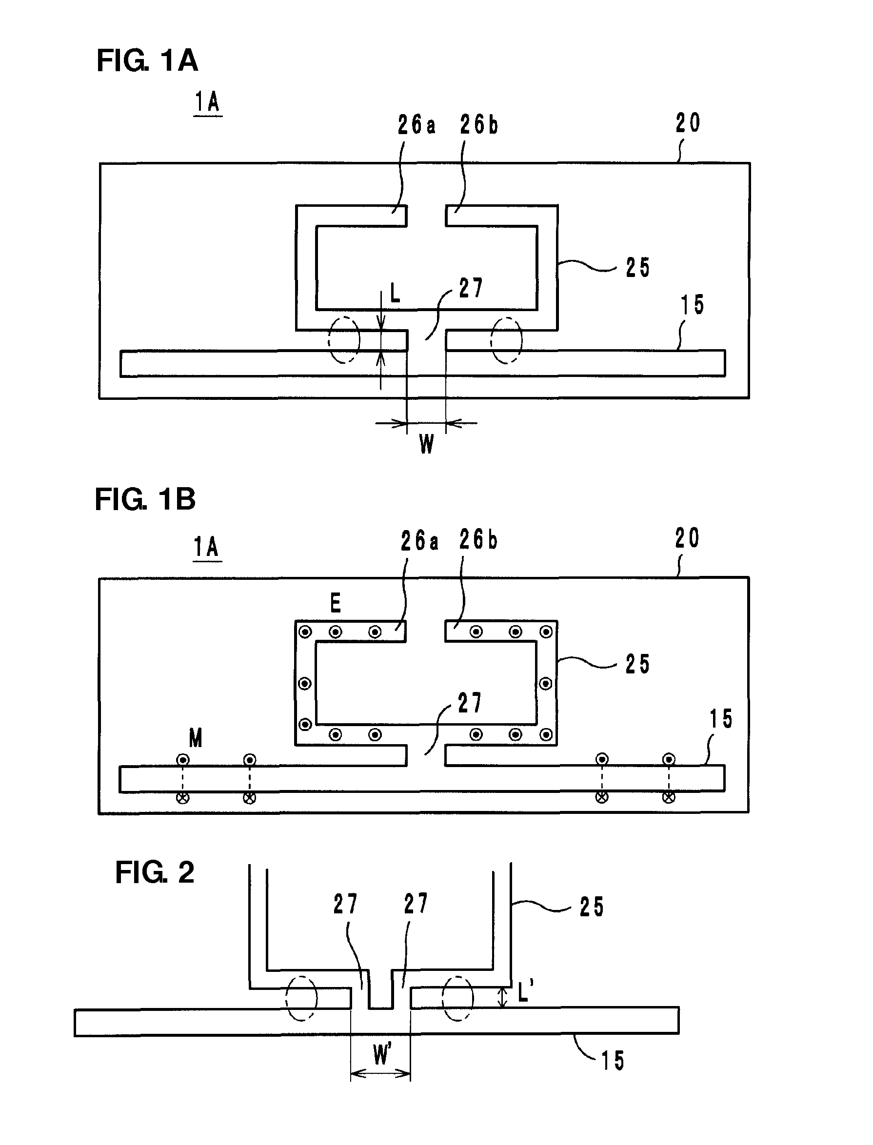
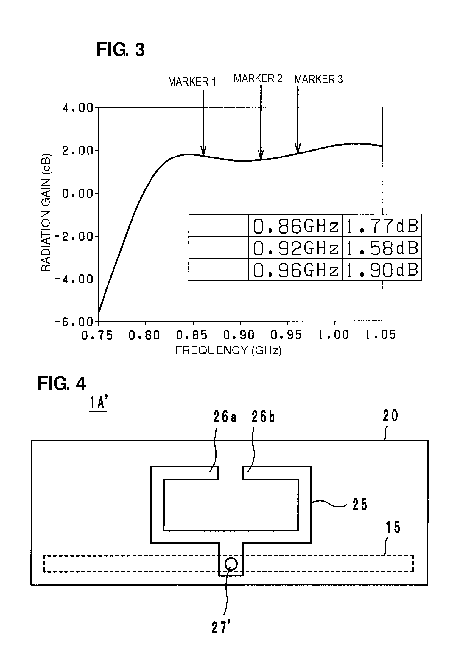
[0024]FIG. 1A shows a composite antenna 1A according to a first preferred embodiment of the present invention. The composite antenna 1A includes a long dipole antenna 15 and a loop antenna 25 provided on a substrate 20, such as a PET film, for example.
[0025]The dipole antenna 15 and the loop antenna 25 are preferably formed by bonding a thin metal plate preferably made of a conductive material, such as an aluminum or copper foil, for example, on the substrate 20 and performing patterning, or by applying conductive paste preferably of Al, Cu, or Ag, for example, on the substrate 20, or by patterning a film provided by plating with those metals, for example.
[0026]The loop antenna 25 includes a pair of end portions 26a and 26b facing each other, and a portion of the loop antenna 25 is electrically connected to the dipole antenna 15 via a connection portion 27. On the end portions 26a and 26b of the loop antenna 25, although not shown, a wireless IC chip, or a high frequency module havi...
second preferred embodiment
[0042]FIG. 5 shows a composite antenna 1B according to a second preferred embodiment of the present invention. In the composite antenna 1B, end portions 16a and 16b of a dipole antenna 15 are bent along the sides of a loop antenna 25 and arranged such that the loop antenna 25 is sandwiched between the end portions 16a and 16b at both sides thereof in plan view. The other portions of the structure are similar to those of the first preferred embodiment described above, and their functions and effects are also similar to those of the first preferred embodiment described above.
[0043]In the second preferred embodiment, in particular, a reduction in size is achieved by bending the end portions 16a and 16b of the dipole antenna 15 toward the loop antenna 25. By making the end portions 16a and 16b of the dipole antenna 15 oriented in a predetermined direction, the directivity in a predetermined direction may be increased. Furthermore, since the bent portions including the end portions 16a a...
third preferred embodiment
[0044]FIG. 6 shows a composite antenna 1C according to a third preferred embodiment of the present invention. In the composite antenna 1C, the end potions include wide portions 17a and 17b. The other portions of the structure are similar to those of the first preferred embodiment described above, and their functions and effects are also similar to those of the first preferred embodiment described.
PUM
 Abstract
Description
Claims
Application Information
 - R&D
- Intellectual Property
- Life Sciences
- Materials
- Tech Scout
- Unparalleled Data Quality
- Higher Quality Content
- 60% Fewer Hallucinations
Browse by: Latest US Patents, China's latest patents, Technical Efficacy Thesaurus, Application Domain, Technology Topic, Popular Technical Reports.
© 2025 PatSnap. All rights reserved.Legal|Privacy policy|Modern Slavery Act Transparency Statement|Sitemap|About US| Contact US: help@patsnap.com


