Composite antenna

a technology of composite antennas and antennas, applied in the structure of resonant antennas, instruments, radiating elements, etc., can solve the problems of short distance communication and unstable communication, and achieve the effects of improving radiation characteristics and communication performance, stabilizing communication performance, and high coupling between the two antennas

Active Publication Date: 2010-11-11
MURATA MFG CO LTD
View PDF82 Cites 77 Cited by
  • Summary
  • Abstract
  • Description
  • Claims
  • Application Information

AI Technical Summary

Benefits of technology

[0007]To overcome the problems described above, preferred embodiments of the present invention provide a composite antenna achieving favorable radiation characteristics and communication performance that can be used for short distance communication as well as for long distance communication.
[0009]In the composite antenna, the dipole antenna can perform long distance communication by utilizing an electric field, and the loop antenna can perform short distance communication by utilizing a magnetic field. In addition, since the loop antenna and the dipole antenna are connected at a point at which the amplitude of a current flowing in the loop antenna has a maximum value, the degree of coupling between the two antennas is high and the radiation characteristics and communication performance are improved.
[0010]The composite antenna according to various preferred embodiments of the present invention enables long distance communication using the dipole antenna and short distance communication using the loop antenna. In addition, the use of the two antennas stabilizes the communication performance and increases the coupling between the two antennas, thereby providing favorable radiation characteristics and communication performance.

Problems solved by technology

However, the above-described tag antenna causes a problem in short distance communication, since a dipole antenna works better as a long distance electric field antenna.
In addition, a dipole antenna has a problem in which a point at which an electric field becomes zero, i.e., a “null point” is generated in accordance with operating conditions such as a communication distance, leading to unstable communication.

Method used


Image

  • Composite antenna
  • Composite antenna
  • Composite antenna

Examples


first preferred embodiment

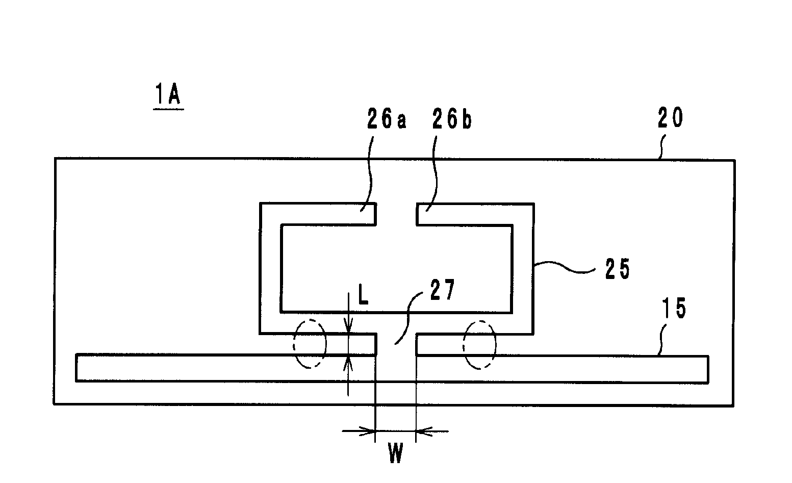
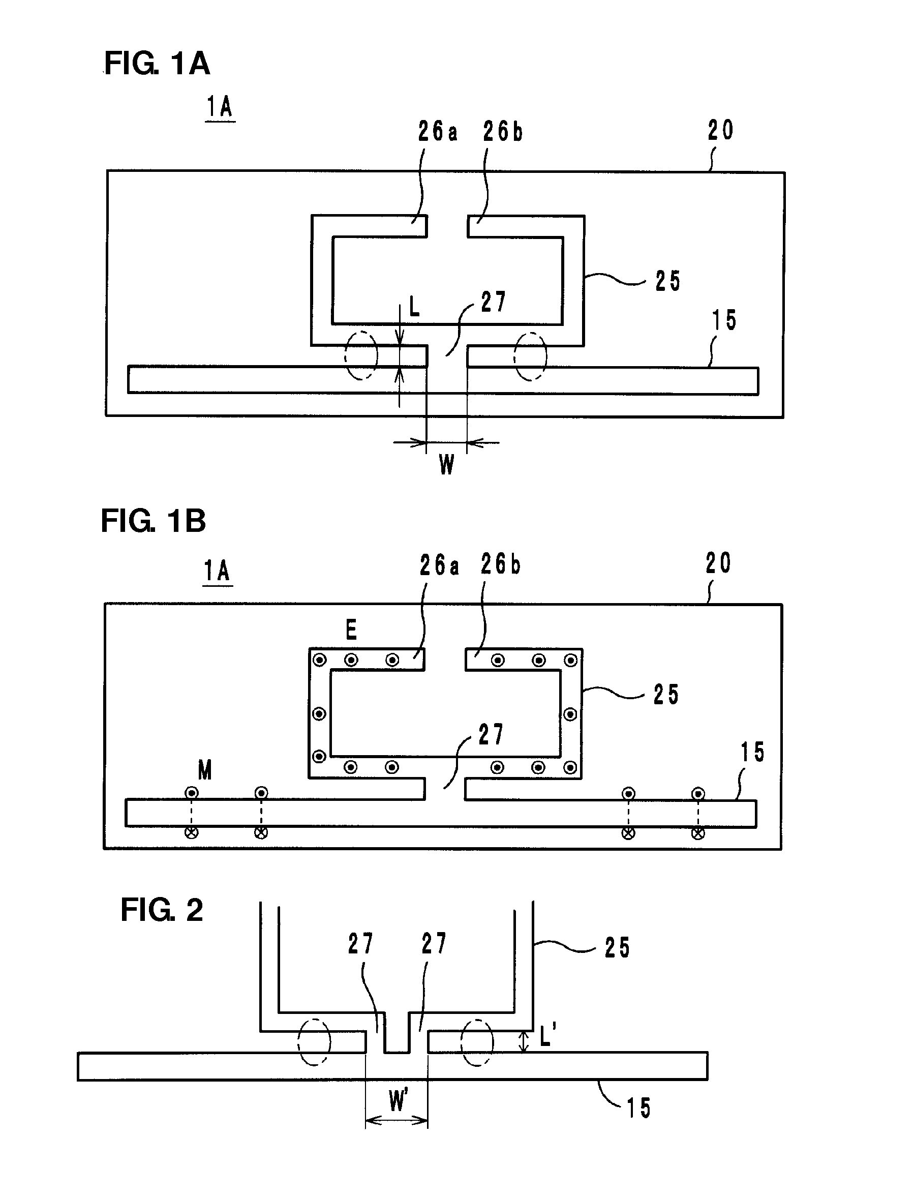
[0024]FIG. 1A shows a composite antenna 1A according to a first preferred embodiment of the present invention. The composite antenna 1A includes a long dipole antenna 15 and a loop antenna 25 provided on a substrate 20, such as a PET film, for example.

[0025]The dipole antenna 15 and the loop antenna 25 are preferably formed by bonding a thin metal plate preferably made of a conductive material, such as an aluminum or copper foil, for example, on the substrate 20 and performing patterning, or by applying conductive paste preferably of Al, Cu, or Ag, for example, on the substrate 20, or by patterning a film provided by plating with those metals, for example.

[0026]The loop antenna 25 includes a pair of end portions 26a and 26b facing each other, and a portion of the loop antenna 25 is electrically connected to the dipole antenna 15 via a connection portion 27. On the end portions 26a and 26b of the loop antenna 25, although not shown, a wireless IC chip, or a high frequency module havi...

second preferred embodiment

[0042]FIG. 5 shows a composite antenna 1B according to a second preferred embodiment of the present invention. In the composite antenna 1B, end portions 16a and 16b of a dipole antenna 15 are bent along the sides of a loop antenna 25 and arranged such that the loop antenna 25 is sandwiched between the end portions 16a and 16b at both sides thereof in plan view. The other portions of the structure are similar to those of the first preferred embodiment described above, and their functions and effects are also similar to those of the first preferred embodiment described above.

[0043]In the second preferred embodiment, in particular, a reduction in size is achieved by bending the end portions 16a and 16b of the dipole antenna 15 toward the loop antenna 25. By making the end portions 16a and 16b of the dipole antenna 15 oriented in a predetermined direction, the directivity in a predetermined direction may be increased. Furthermore, since the bent portions including the end portions 16a a...

third preferred embodiment

[0044]FIG. 6 shows a composite antenna 1C according to a third preferred embodiment of the present invention. In the composite antenna 1C, the end potions include wide portions 17a and 17b. The other portions of the structure are similar to those of the first preferred embodiment described above, and their functions and effects are also similar to those of the first preferred embodiment described.


PUM


Abstract

A composite antenna achieves favorable radiation characteristics and favorable communication performance, and can be used in short distance communication as well as long distance communication. The composite antenna includes a dipole antenna having an elongated shape, a loop antenna including at least one pair of opposing end portions, and a connection portion arranged to connect the dipole antenna and a point of the loop antenna at which the amplitude of a current flowing in the loop antenna has a maximum value. The dipole antenna performs long distance communication utilizing an electric field, and the loop antenna performs short distance communication utilizing a magnetic field. This composite antenna may be used as a wireless IC device in RFID systems.

Description

BACKGROUND OF THE INVENTION[0001]1. Field of the Invention[0002]The present invention relates to a composite antenna, and in particular, to a composite antenna that can be used for radio frequency identification (RFID) systems.[0003]2. Description of the Related Art[0004]RFID systems, for use as article management systems, have been developed in which non-contact communication and information transmission are performed between a reader / writer generating an induction field and an IC chip (also called an IC tag or a wireless tag) that stores predetermined information and is attached to an article or a container. The IC chip can communicate with a reader / writer by being connected to an antenna.[0005]As a tag antenna for mounting an IC chip, the tag antenna disclosed in Japanese Unexamined Patent Application Publication No. 2006-295879 is known. This tag antenna includes an inductor and a dipole antenna. The dipole antenna has wide portions at both ends thereof, and the length of the di...

Claims


Application Information

Patent Timeline
Patent Type & Authority Applications(United States)
IPC IPC(8): H01Q1/00
CPCG06K19/07749G06K19/07767G06K19/07777G06K19/07779G06K19/07786H01Q9/285H01Q1/38H01Q7/00H01Q9/16H01Q9/26H01Q1/2225
Inventor KATO, NOBORU
Owner MURATA MFG CO LTD
Why Eureka
Try Eureka