Electrical switching apparatus and mounting assembly therefor

a technology of electrical equipment and mounting assembly, which is applied in the direction of protective switch details, electrical apparatus construction details, casings/cabinets/drawers of electrical apparatus, etc., can solve the problems of maintenance personnel injury, electrical equipment damage, operator danger,

Active Publication Date: 2012-05-15
EATON INTELLIGENT POWER LTD
View PDF13 Cites 8 Cited by
  • Summary
  • Abstract
  • Description
  • Claims
  • Application Information

AI Technical Summary

Benefits of technology

[0008]These needs and others are met by embodiments of the disclosed concept, which are directed to a mounting assembly for electrical switching apparatus, such as circuit breakers. Among other benefits, the mounting assembly enables the installation (e.g., mounting) of equipment such as, for example and without limitation, remote operating apparatus, by providing access to the circuit breaker without requiring the circuit breaker cover or switchgear enclosure to be opened, and without requiring modification to the existing switchgear enclosure, circuit breaker or other electrical equipment.
[0010]The at least one bracket may comprise a retaining plate, wherein the retaining plate includes a first side structured to face the exterior of the housing, and a second side disposed opposite the first side. The expansion member may comprise a resilient element, and the actuator may comprise a lever assembly, a number of generally planar members, and a number of fasteners fastening the resilient element and the generally planar members to the lever assembly. The lever assembly may be substantially disposed on the second side of the retaining plate, and the resilient element may be disposed between a corresponding one of the generally planar members and the first side of the retaining plate. The lever assembly may include a handle, wherein the handle is movable between a first position corresponding to the actuator being disposed in the unactuated position, and a second position corresponding to the actuator being disposed in the actuated position. When the handle is moved from the first position toward the second position, the corresponding one of the generally planar members may move toward the first side of the retaining plate, thereby compressing the resilient element therebetween and causing the resilient element to expand outwardly.
[0011]The bracket assembly may further comprise an accessory housing structured to mount an accessory in a predetermined position with respect to the electrical switching apparatus. The housing of the electrical switching apparatus may further comprise a cover, and the electrical switching apparatus may further comprise a remote operating apparatus. The accessory housing may mount a number of components for the remote operating apparatus in a predetermined position with respect to the electrical switching apparatus to enable the remote operating apparatus to operate the electrical switching apparatus remotely, without requiring the cover of the electrical switching apparatus to be opened.

Problems solved by technology

Improper maintenance procedures (e.g., failure to first de-energize or turn the circuit breaker OFF) could cause serious injury to maintenance personnel and damage to the electrical equipment.
However, among other disadvantages, known devices of this type require modification of the existing switchgear enclosure, circuit breaker or electrical equipment, are mounted on the door or cover of the enclosure or circuit breaker by a relatively complex mounting hardware assembly, and / or require the door or cover to be opened potentially subjecting the operator to danger.

Method used


Image

  • Electrical switching apparatus and mounting assembly therefor
  • Electrical switching apparatus and mounting assembly therefor
  • Electrical switching apparatus and mounting assembly therefor

Examples


Embodiment Construction

[0018]Directional phrases used herein, such as, for example, front, back, top, bottom and derivatives thereof, relate to the orientation of the elements shown in the drawings and are not limiting upon the claims unless expressly recited therein.

[0019]As employed herein, the term “fastener” refers to any suitable connecting or tightening mechanism expressly including, but not limited to, screws, bolts and the combinations of bolts and nuts (e.g., without limitation, lock nuts) and bolts, washers and nuts.

[0020]As employed herein, the statement that two or more parts are “coupled” together shall mean that the parts are joined together either directly or joined through one or more intermediate parts.

[0021]As employed herein, the term “number” shall mean one or an integer greater than one (i.e., a plurality).

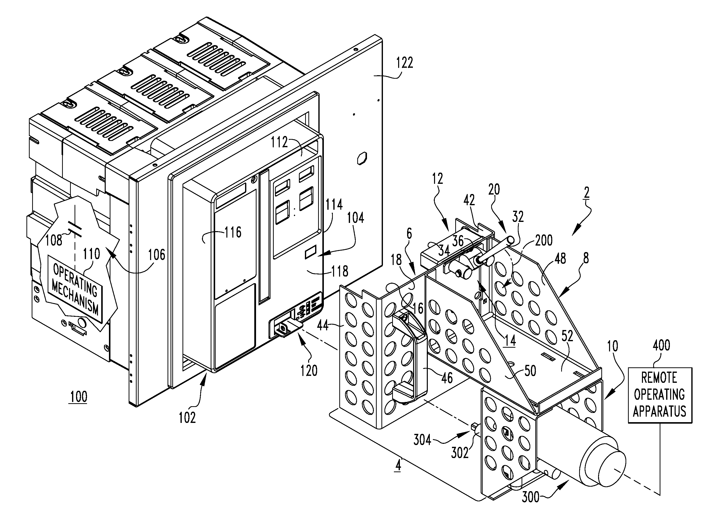
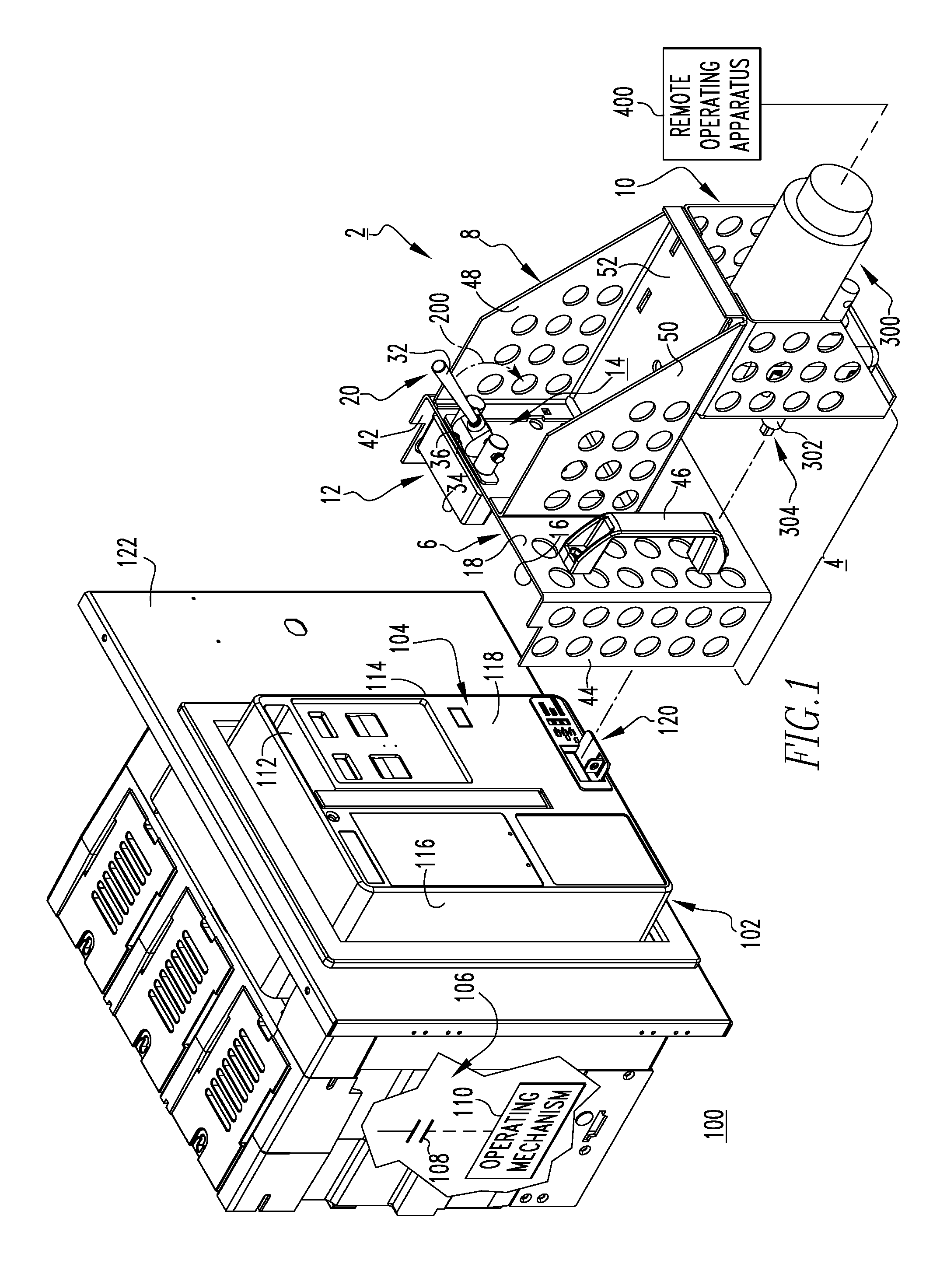
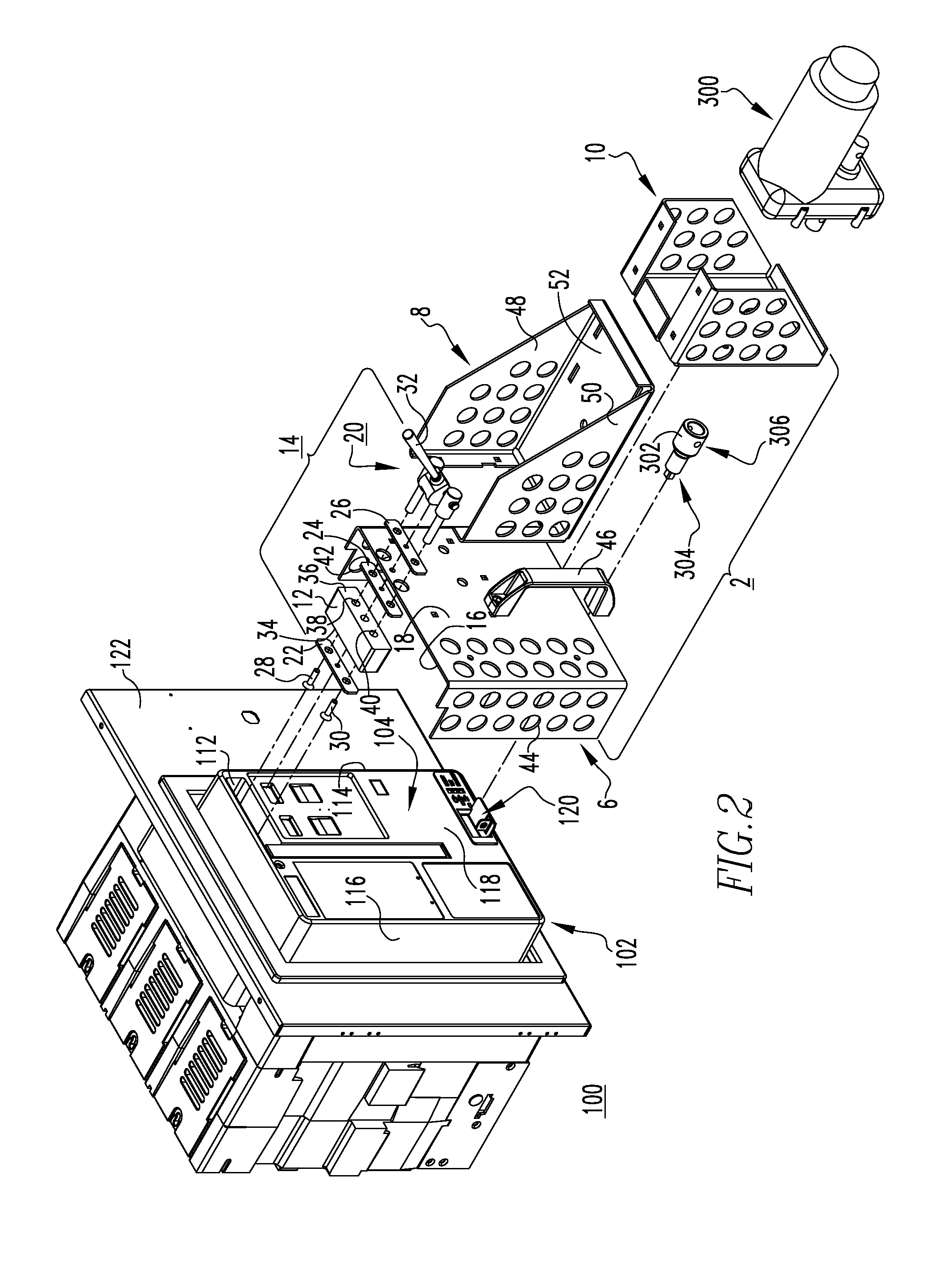
[0022]FIG. 1 shows a mounting assembly 2 for an electrical switching apparatus such as, for example and without limitation, a circuit breaker 100. In the example shown and described...


PUM


Abstract

A mounting assembly is provided for an electrical switching apparatus, such as a circuit breaker. The circuit breaker includes a housing having an exterior and an interior, separable contacts disposed in the interior, and an operating mechanism structured to open and closed the separable contacts. The exterior of the housing includes a recess. The mounting assembly includes a bracket assembly having at least one bracket, an expansion member coupled to a corresponding one of the at least one bracket and being disposed within the recess on the exterior of the housing, and an actuator movably coupled to the expansion member. The actuator is movable between an actuated position corresponding to the expansion member expanding outwardly within the recess to secure the mounting assembly to the circuit breaker, and an unactuated position corresponding to the expansion member not being expanded and the mounting assembly being removable from the circuit breaker.

Description

BACKGROUND[0001]1. Field[0002]The disclosed concept relates generally to electrical switching apparatus and, more particularly, to electrical switching apparatus, such as circuit breakers. The disclosed concept also relates to mounting assemblies for circuit breakers.[0003]2. Background Information[0004]Electrical switching apparatus used in power distribution systems are often mounted within a switchgear enclosure either individually or in combination with other switchgear (e.g., without limitation, circuit switching devices and circuit interrupters such as circuit breakers, contactors, motor starters, motor controllers and other load controllers).[0005]Some electrical switching apparatus such as, for example, some medium-voltage and low-voltage circuit breakers, can be relatively large. In order to facilitate movement (e.g., installation; removal; maintenance), some circuit breakers are commonly coupled to draw-out mechanisms which permit such circuit breakers to be drawn out of t...

Claims


Application Information

Patent Timeline
Patent Type & Authority Patents(United States)
IPC IPC(8): H05K7/00
CPCH01H71/56H01H2071/565
Inventor COOMER, JARROD LYLEMETCALF, DAVID AARON
Owner EATON INTELLIGENT POWER LTD
Why Eureka
Try Eureka