Calibrated vision based robotic system

a robotic system and vision technology, applied in the field of vision based robotic system, can solve problems such as prone to errors, disk drive failure, and undesirable human labor us

Active Publication Date: 2012-05-15
WESTERN DIGITAL TECH INC
View PDF23 Cites 53 Cited by
  • Summary
  • Abstract
  • Description
  • Claims
  • Application Information

AI Technical Summary

Problems solved by technology

Robots can often perform repeated tasks with precision and efficiency that is generally not achievable through the use of human labor.
Further, robots can be used in environments where manufacturing techniques for picking, placing, and assembling very small components make the use of human labor undesirable.
For example, this is particularly important in disk drive manufacturing where misplaced components may result in scraping during the assembly process possibly contaminating the disk drive and resulting in disk drive failure.
However, in present robotic disk drive manufacturing, components are picked and placed by a robot from a taught point using a gripper, which may be prone to error.
Thus, although attempts to improve robot accuracy are presently being made, these present techniques are typically tedious, time-consuming, undesirably expensive, and often do not provide an acceptable level of accuracy.
Unfortunately, for high technology device manufacturing, such as disk drive manufacturing, that requires very high accuracy to avoid scraping and contamination, these present techniques are not acceptable.

Method used


Image

  • Calibrated vision based robotic system
  • Calibrated vision based robotic system
  • Calibrated vision based robotic system

Examples


Embodiment Construction

[0016]In the following description, various embodiments of the invention will be described in detail. However, such details are included to facilitate understanding of the invention and to describe exemplary embodiments for implementing the invention. Such details should not be used to limit the invention to the particular embodiments described because other variations and embodiments are possible while staying within the scope of the invention. Furthermore, although numerous details are set forth in order to provide a thorough understanding of the present invention, it will be apparent to one skilled in the art that these specific details are not required in order to practice the present invention. In other instances details such as, well-known electrical structures, circuits, robotic tools, robotic devices, manufacturing devices, mechanical devices, methods, procedures, and components are not described in detail, or are shown in block diagram form, in order not to obscure the pres...


PUM

PropertyMeasurementUnit
distanceaaaaaaaaaa
movementaaaaaaaaaa
whiteaaaaaaaaaa

Abstract

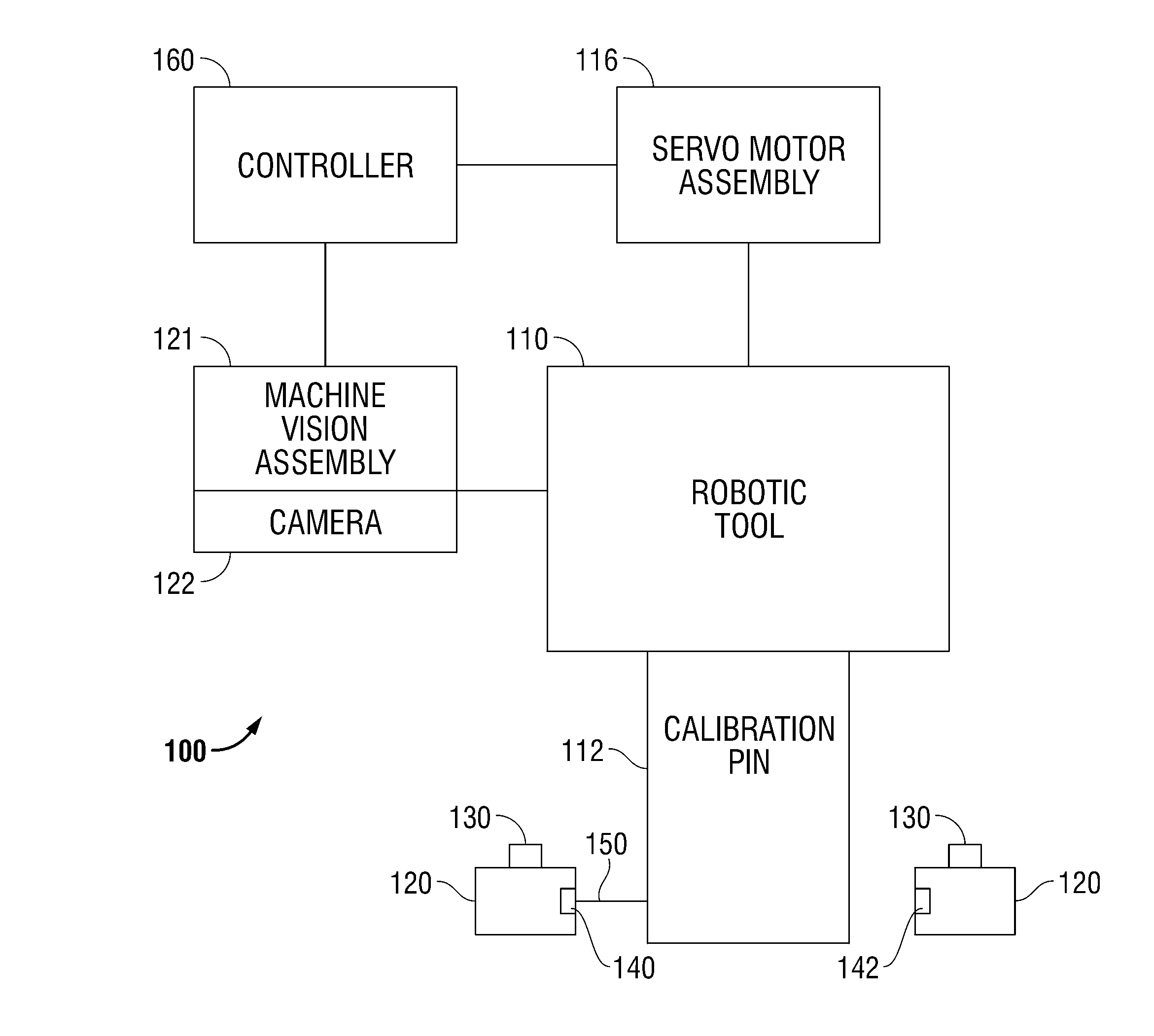
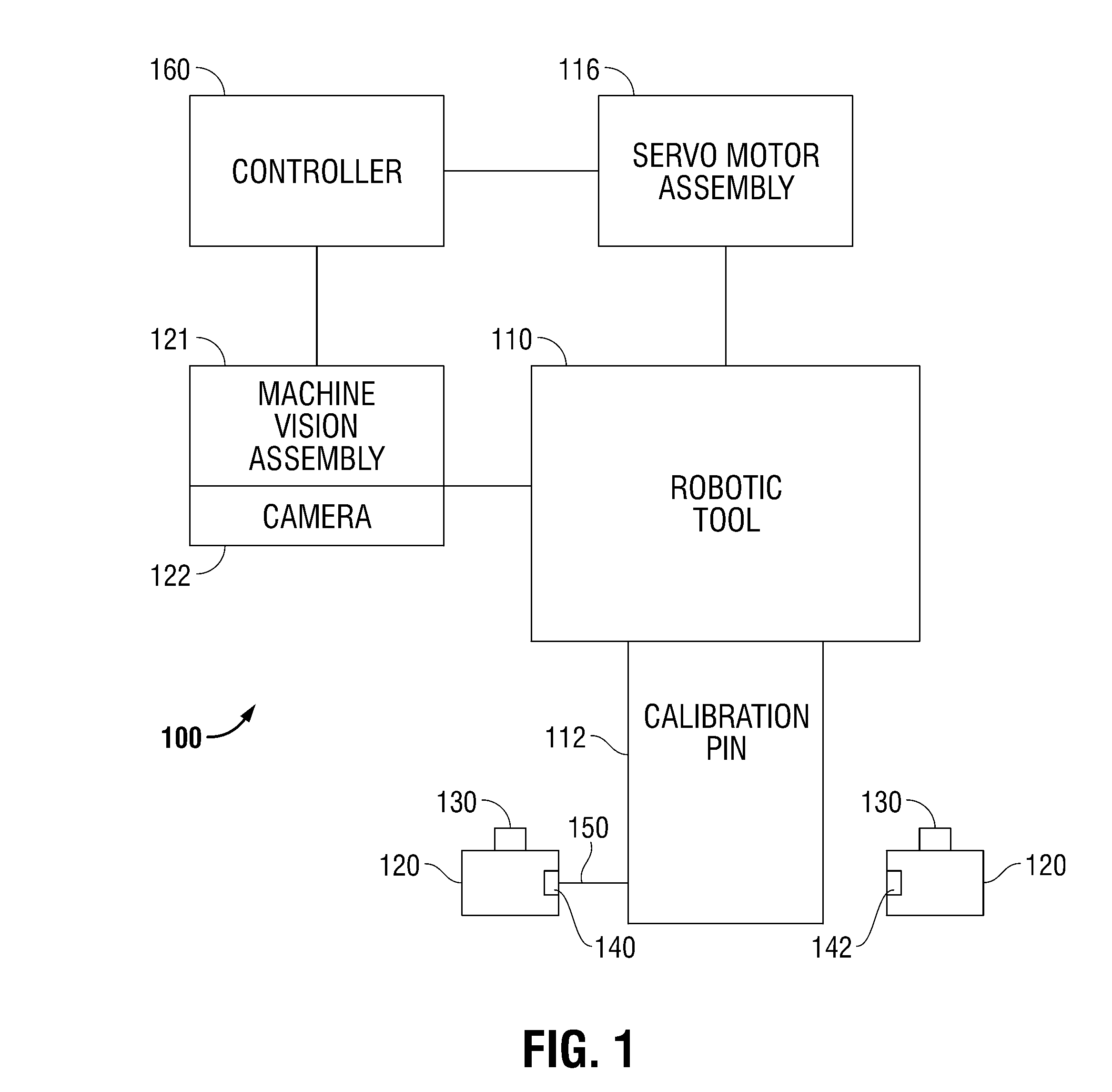
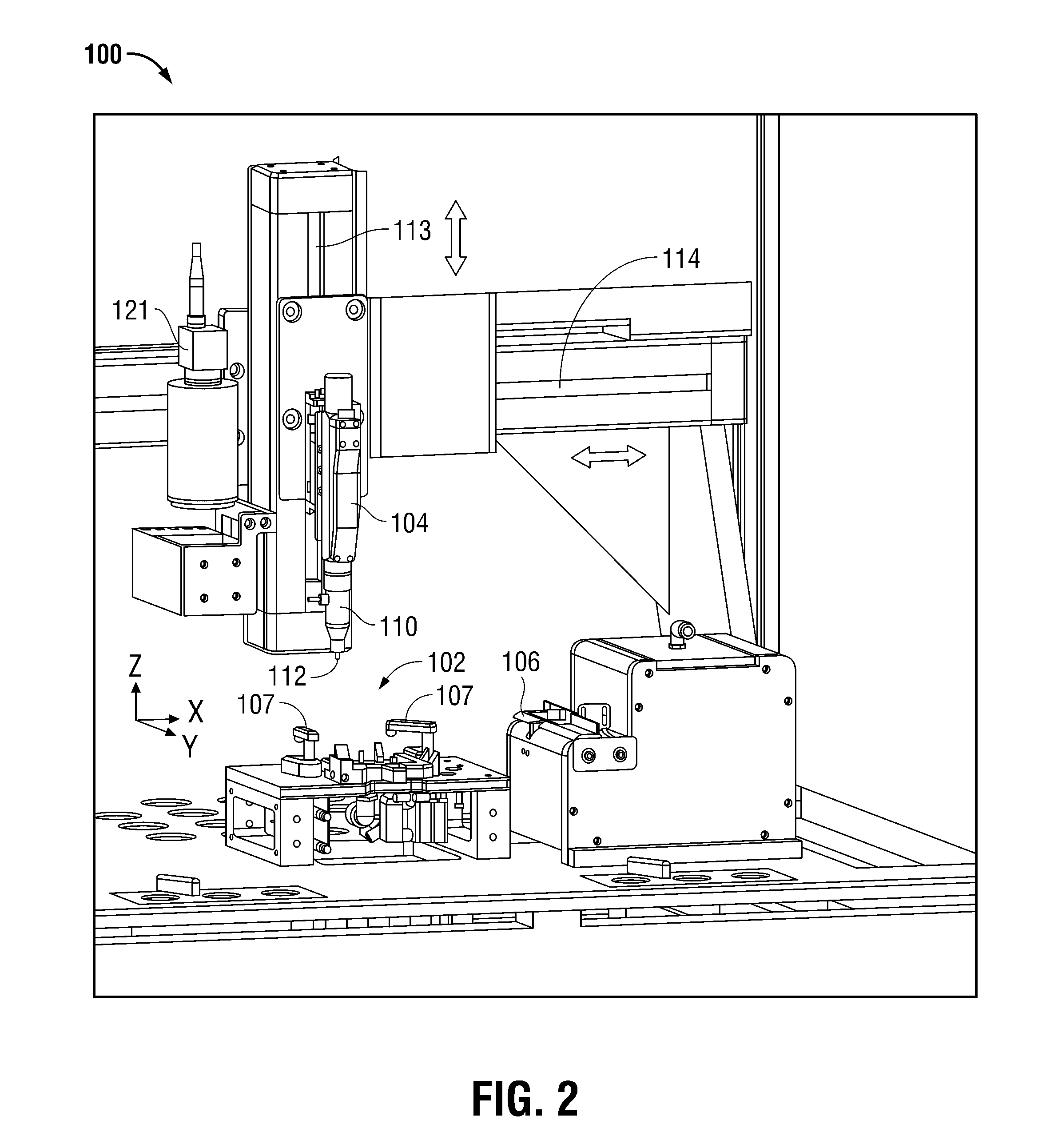
A method of calibrating a vision based robotic system. The method includes engaging a calibration pin with a robotic tool and moving the calibration pin to a calibration block that includes at least one set of optical sensors having an optical transmitter to transmit an optical beam and an optical receiver to receive the optical beam. Further, the transmitted optical beam includes a center point. The method further includes: moving the calibration pin to the center point of the transmitted optical beam; determining a calibration pin center position relative to the robotic tool; and commanding a machine vision assembly having a camera to capture an image of a plurality of camera reading points of the calibration block and to determine a camera center position.

Description

BACKGROUND OF THE INVENTION[0001]The use of robotic systems in automated manufacturing has become increasingly important in high technology device manufacturing. Robots can often perform repeated tasks with precision and efficiency that is generally not achievable through the use of human labor. Further, robots can be used in environments where manufacturing techniques for picking, placing, and assembling very small components make the use of human labor undesirable.[0002]For example, this is particularly important in disk drive manufacturing where misplaced components may result in scraping during the assembly process possibly contaminating the disk drive and resulting in disk drive failure. This is particularly true for small-form-factor disk drives that require very high accuracy assembly techniques.[0003]Robots used in disk drive manufacturing by picking, placing, and assembling components are generally well known in the art. However, in present robotic disk drive manufacturing,...

Claims


Application Information

Patent Timeline
Patent Type & Authority Patents(United States)
IPC IPC(8): G05B15/00
CPCB25J9/1692G05B2219/39025G05B2219/40624
Inventor VANGAL-RAMAMURTHY, JAMBUNATHANFOSTER, ROBERT E.
Owner WESTERN DIGITAL TECH INC
Why Eureka
Try Eureka