Method for controlling gear change during shifting rule or variogram switching

a technology of gear change and shifting rule, applied in the direction of electric/magnetic computing, analogue processes for specific applications, instruments, etc., can solve problems such as surprise the operator

Inactive Publication Date: 2012-05-15
RENAULT SA
View PDF58 Cites 2 Cited by
  • Summary
  • Abstract
  • Description
  • Claims
  • Application Information

AI Technical Summary

Problems solved by technology

A switch of shifting rules or of variograms can be felt immediately by a change of gear ratio, which may surprise the operator.

Method used


Image

  • Method for controlling gear change during shifting rule or variogram switching
  • Method for controlling gear change during shifting rule or variogram switching
  • Method for controlling gear change during shifting rule or variogram switching

Examples


Embodiment Construction

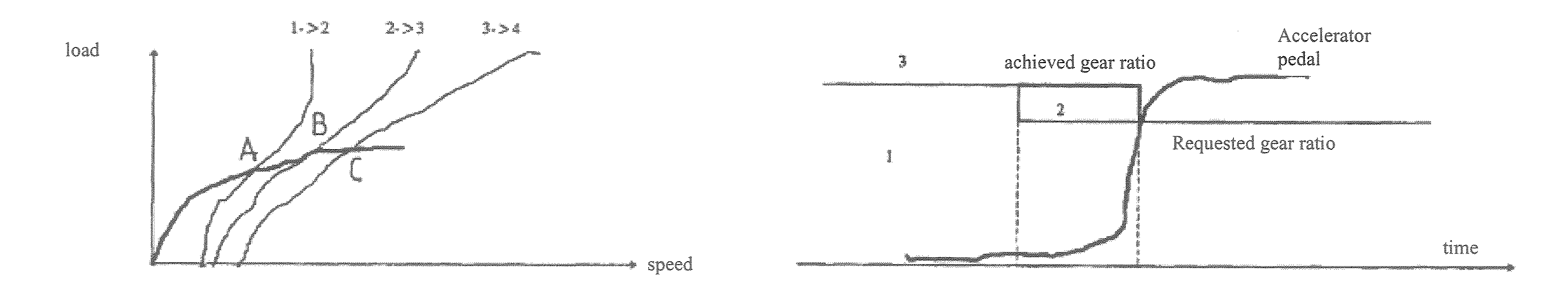
[0017]FIG. 1 illustrates the changes of gear ratios of a transmission with discrete gear ratios, for example, when the vehicle is in an accelerating phase. In this non-limitative example of a sequence, the shifts take place successively at points A, B and C of intersection of curves 1 / 2, 2 / 3, 3 / 4 in a plane of vehicle travel speed versus engine load. According to the teaching of French Patent 2545567, the downshift curves (not illustrated on the diagram) would be offset to the left relative to the corresponding upshift curves, in order to limit the phenomena of oscillation between two consecutive gear ratios, or in other words the “hunting” phenomena.

[0018]In the case of an auto-adaptive transmission, which is programmed with a plurality of shifting rules, several sets of curves corresponding to each shifting rule are also present in one plane. However, the sets of curves are offset relative to one another. In the case of a switch of shifting rule, therefore, a change of gear ratio ...


PUM


Abstract

The inventive method for controlling the gear change of an automatic gearbox provided with distinct shifting rules or variograms used according to a vehicle operating conditions consists in detecting and carrying out gear shifting requests sequential to the shifting rule or variogram switching, subject to the application of specific conditions only.

Description

[0001]The present invention relates to the control of automatic vehicle transmissions with discrete ear ratios and also continuous variations, of the automatic gearbox type, robotized gearbox type or continuously or infinitely variable transmission.BACKGROUND[0002]More precisely, it relates to the control of changes of gear ratio of an automatic transmission programmed with distinct shifting rules or variograms, applied according to the operating conditions of the vehicle.[0003]According to a traditional system, illustrated in particular by French Patent 2545567, the decisions to change year ratios of a transmission with discrete gear ratios are made when a point representative of the operation of the transmission in a coordinate plane defined by speed of travel of the vehicle and engine load (accelerator pedal position, engine torque power etc.) intersects an upshift curve or a downshift curve. In this representation, the set of upshift and downshift curves defines a shifting rule ...

Claims


Application Information

Patent Timeline
Patent Type & Authority Patents(United States)
IPC IPC(8): G06F7/00G06F17/00F16H59/08F16H59/18F16H59/46F16H61/02F16H61/16F16H61/66
CPCF16H61/0213F16H61/66254B60W2540/30F16H59/18F16H59/46F16H61/16Y10T477/6934F16H2059/082F16H2059/003F16H2061/0227Y10T477/692F16H61/66F16H61/02F16H61/00
Inventor TAFFIN, CHRISTIANPOISSON, CARINE
Owner RENAULT SA
Why Eureka
Try Eureka