
Floor display

a technology for floor displays and floor surfaces, applied in the field of floor displays, can solve the problems of difficult removal, residue of adhesive on the floor, and easy wear of edges and corners of products, and achieve the effects of reducing hardness, increasing non-slip properties, and saving costs and tim

Active Publication Date: 2012-05-22
COMAX
View PDF6 Cites 1 Cited by
  • Summary
  • Abstract
  • Description
  • Claims
  • Application Information

AI Technical Summary

Benefits of technology

"The present invention provides a floor display that is user-friendly, easy to exchange, and provides a good seal against dirt and moisture. The floor display comprises a window plate, a baseplate, and a flexible frame that holds them together. The frame is non-releasably connected to the window plate and the baseplate on at most two peripheral edge sides. The frame is made from a more flexible material and can be pushed all the way to the bonded edge sides, making it easy to position an image carrier. The baseplate is made from a material that is securely bonded to the frame and has a substantially the same expansion coefficient. The frame and the baseplate can be produced from the same material, and the non-slip profile can be molded onto the baseplate in a single operation at the same time as the frame. The invention also relates to a method for producing the floor display."

Problems solved by technology

However, stickers have the drawbacks of not being reusable, that it is a specialist job to apply them to the floor, in particular the edges and corners of the product are susceptible to wear, and once the stickers have been removed they can leave behind residues of adhesive on the floor, which are difficult to remove.
One drawback in this context is that the ease of use leaves something to be desired.
For example, exchanging an image carrier between the plates is difficult and takes up a relatively long time.
This problem is exacerbated if the dimensions of the display increase, for example, to Al format, which is often used in floor displays.
One drawback with the clamping retaining of the baseplate is that with relatively great lengths, such as in the said floor displays, the frame with clamping edge also has to be relatively high, in order to be able to offer sufficient resistance to the relatively high forces which are exerted on the plates and the frame, for example by people walking over the display or shopping trolleys being pushed across it or when the display is being picked up.
The required rigidity of the frame is, however, disadvantageous when an image carrier is being exchanged.
One drawback in this context is that the positive locking of the window plate requires the frame to be even higher and wider and made from an even more rigid material, with all the associated drawbacks described above.
This is disadvantageous for dustproofing and watertightness.
Furthermore, the plates and the frame can easily be displaced with respect to one another if a person collides with the vertical edge which projects above the window plate.
Furthermore, the vertical edge has the drawback that dirt can accumulate behind it and that water and cleaning agents remain present inside the edges after cleaning, and that the corners and edges are difficult to clean.

Method used


Image

  • Floor display
  • Floor display
  • Floor display

Examples


Embodiment Construction

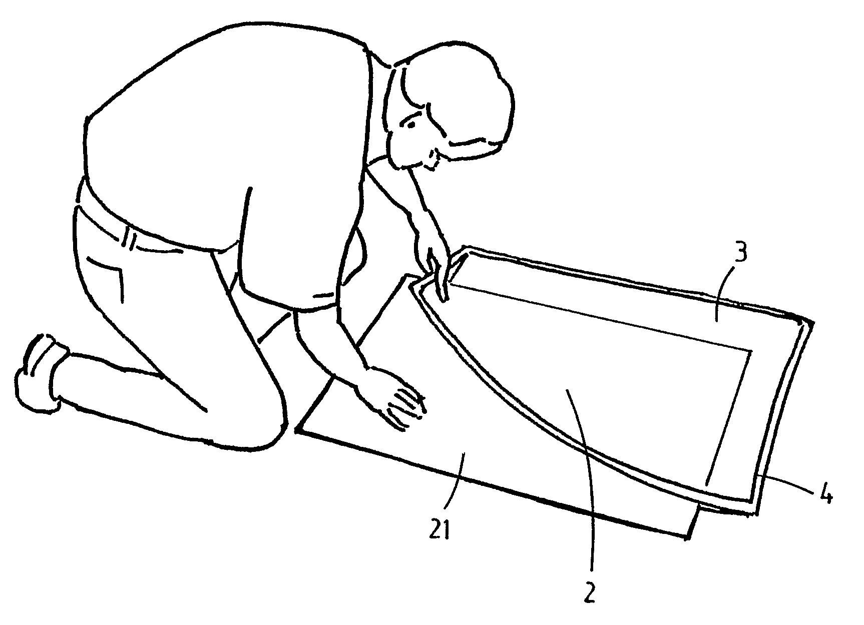
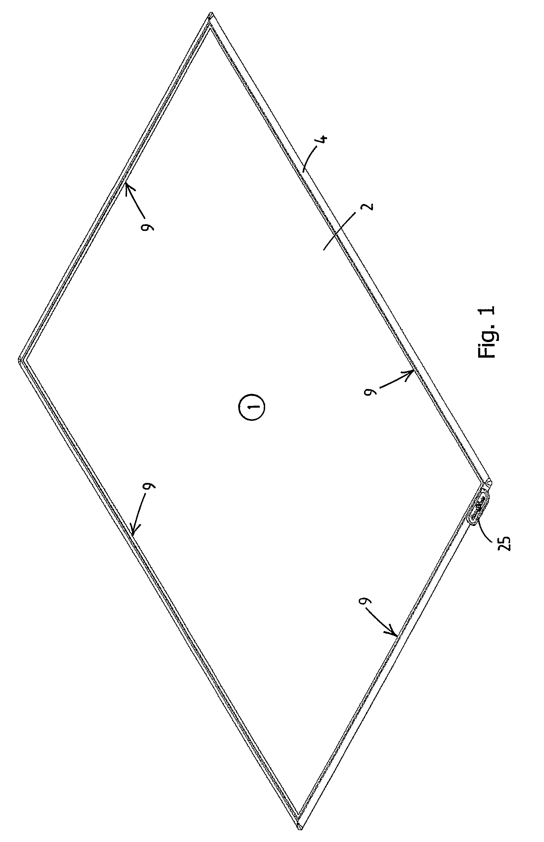
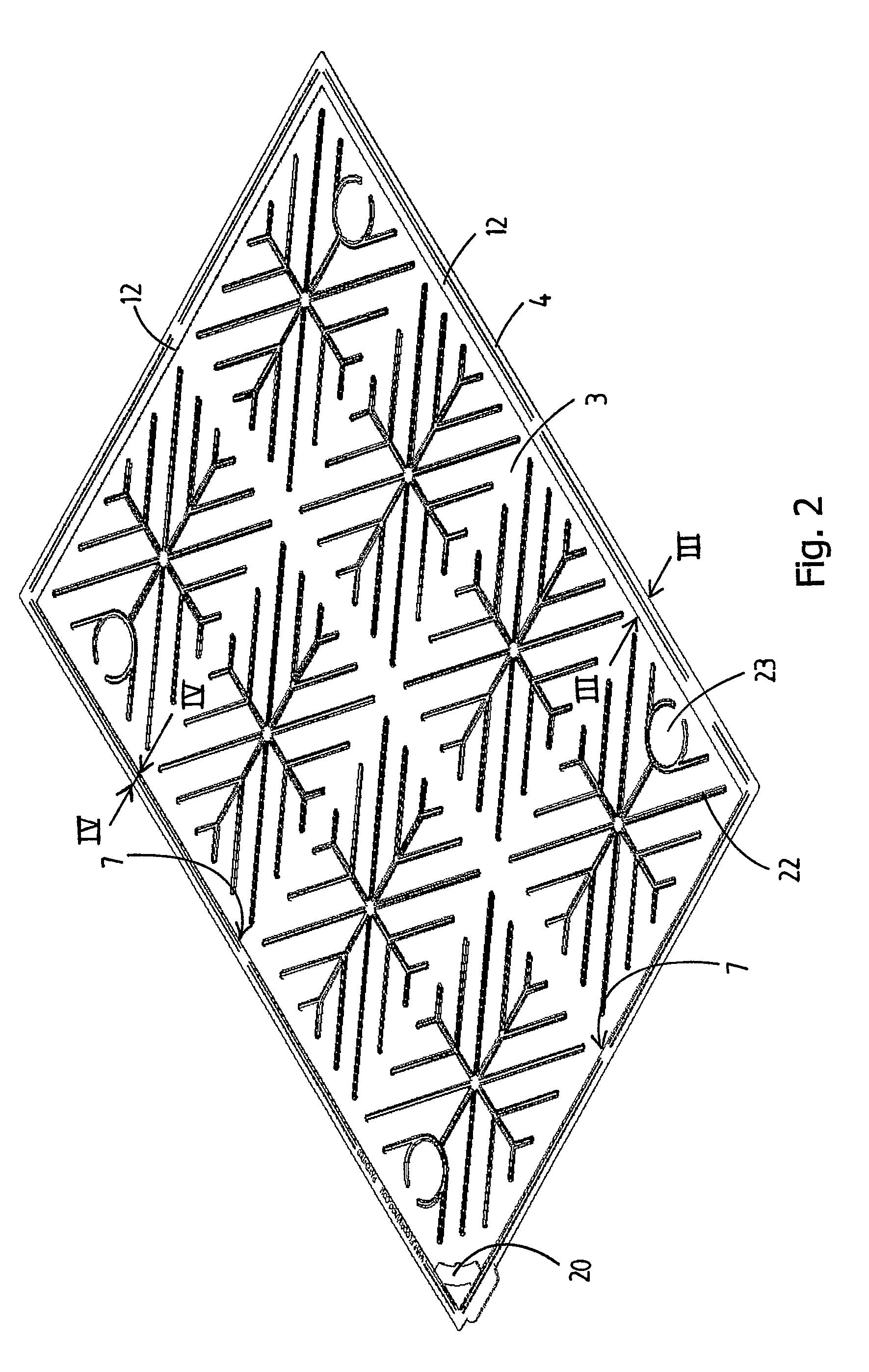
[0037]In FIGS. 1-8, the floor display is denoted overall by reference numeral 1. The substantially rectangular floor display 1 comprises a window plate 2, a baseplate 3 and a moulded-on frame 4. The baseplate 3 is designed to be less wide and long than the window plate 2. The materials of the plates 2, 3 are such that the frame material is able to be bonded to the two plates 2, 3 in the molten state and then to set nonreleasably onto it, thereby forming a securely bonded connection.

[0038]During production, the two plates 2, 3 are placed into a suitably shaped mould, in which a cavity is left for the frame 4 to be moulded on in an injection-moulding process. In this case, two adjacent vertical peripheral edge sides 7 of the baseplate 3 are provided with an agent that does not bond to the frame material. After the flexile material which is to form the frame 4 has been injected and set, the situation automatically arises whereby the frame 4 is nonreleasably bonded to the entire vertica...


PUM


Abstract

A floor display comprises a window plate (2) made from a transparent material, a baseplate (3), and a frame made from flexible material, the frame (4) extending around the two plates (2, 3) and holding them together, it being possible for an exchangeable image carrier (21) made of material in sheet or film form to be placed between the plates (2, 3), the frame (4) being nonreleasably connected, by means of a bonded join, to substantially the entire peripheral edge (9) of the window plate (2), and the frame (4) furthermore being nonreleasably connected, by means of a bonded join, to at most two peripheral edge sides (10) of the baseplate (3).

Description

CROSS-REFERENCE TO RELATED APPLICATION[0001]This application is the National Stage of International Application no. PCT / NL2005 / 000293 filed Apr. 20, 2005, which claims the benefit of Netherlands application number 1026008 filed Apr. 22, 2004, the contents of which are incorporated by reference herein.FIELD OF THE INVENTION[0002]The invention relates to a floor display, in particular an interchangeable picture frame for placing on the floor.BACKGROUND OF THE INVENTION[0003]A number of years ago, the Applicant discovered the unexploited possibilities of the floor as an advertising or information surface. To remedy this deficiency, at that time he developed a display which is commercially available under the name FloorWindo.[0004]The FloorWindo is a flat interchangeable picture frame for posters intended to be laid on a floor, in particular on a shop floor. If necessary, a shopping trolley can be pushed over it without the display or image carrier being visibly damaged. Floor advertisi...

Claims


Application Information

Patent Timeline
Patent Type & Authority Patents(United States)
IPC IPC(8): G09F1/00G09F19/22
CPCG09F19/22G09F19/228
Inventor RIETVELD, MATTHIJS ALPHONS
Owner COMAX
Learn More