Mobile or stationary working apparatus with telescopic extension arm elements whose position in relation to one another is detected by RFID technology

a technology of telescopic extension arm and working apparatus, which is applied in the direction of load-engaging elements, portable lifting, instruments, etc., can solve the problems of undesired measuring errors, inability to compact equipment elements, and clear increase of potentiometers, and achieves rapid and simple manner

Inactive Publication Date: 2012-05-22
HIRSCHMANN AUTOMATION AND CONTROL
View PDF12 Cites 8 Cited by
  • Summary
  • Abstract
  • Description
  • Claims
  • Application Information

AI Technical Summary

Benefits of technology

[0007]The invention provides that the detector is designed as a radio detection means comprising a radio base unit on the base of the equipment and further transponders on the telescoping parts. The design of the detector as radio detection means has the basic advantage that it is compact, is subjected to no mechanical wear, and contamination or other adverse influences on the radio detection means do not adversely affect its operation. The radio detection means has the particular advantage that its operation is also not adversely influenced by contamination or by sagging of the telescoping arm with or without a load. Since the radio detection means consists of a radio base unit and further transponders that are designed to operate independently, the latter can be mounted in a rapid and simple manner and replaced just as rapidly in case of a defect.

Problems solved by technology

However, it has the disadvantage that it is subjected to frictional wear, contamination and the like, so that it is prone to error.
It this is to be avoided, a monitoring and cleaning and / or readjustment of the mechanically acting detector is necessary, which is also disadvantageous.
Moreover, the space necessary for accommodating the cable rollers, cable and detector as well as the potentiometer clearly increases with increasing length of the individual telescoping parts, so that this space must be made available and makes it impossible to make the elements of the equipment compact.
Furthermore, in the case of large telescope lengths, that is, a plurality of telescoping parts, sagging of the cable (due to its own weight) results in undesired measuring errors.
However, this optically acting detector has the decisive disadvantage that it on the one hand is very susceptible to dirt, so that the light beam can no longer be completely reflected or not reflected at all if the mirror on the extension arm part is contaminated, which is very frequently the case with construction equipment.
On the other hand, there is the disadvantage in equipment that something can block the light beam between the sending unit and mirror, so that the determination of position relative to one another is to longer possible.
Moreover, there is basically the problem in telescoping arms that they sag, at first because of their own weight when completely extended, which sagging process is amplified even more in the case of a suspended load.
As a result, there is also the danger that the transmitted light beam no longer completely reaches the mirror or does not reach it at all, or in order to avoid this effect extremely comprehensive and complex compensation designs must be used that are also disadvantageous.

Method used


Image

  • Mobile or stationary working apparatus with telescopic extension arm elements whose position in relation to one another is detected by RFID technology
  • Mobile or stationary working apparatus with telescopic extension arm elements whose position in relation to one another is detected by RFID technology

Examples


Embodiment Construction

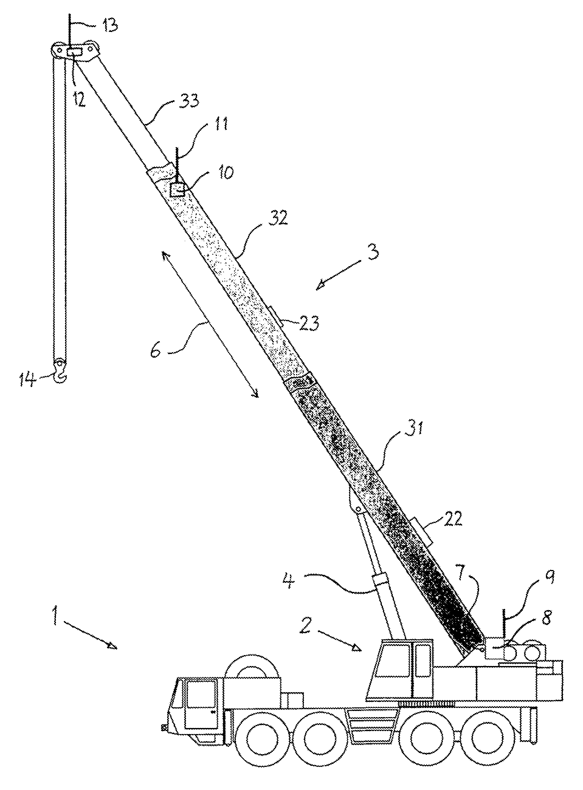
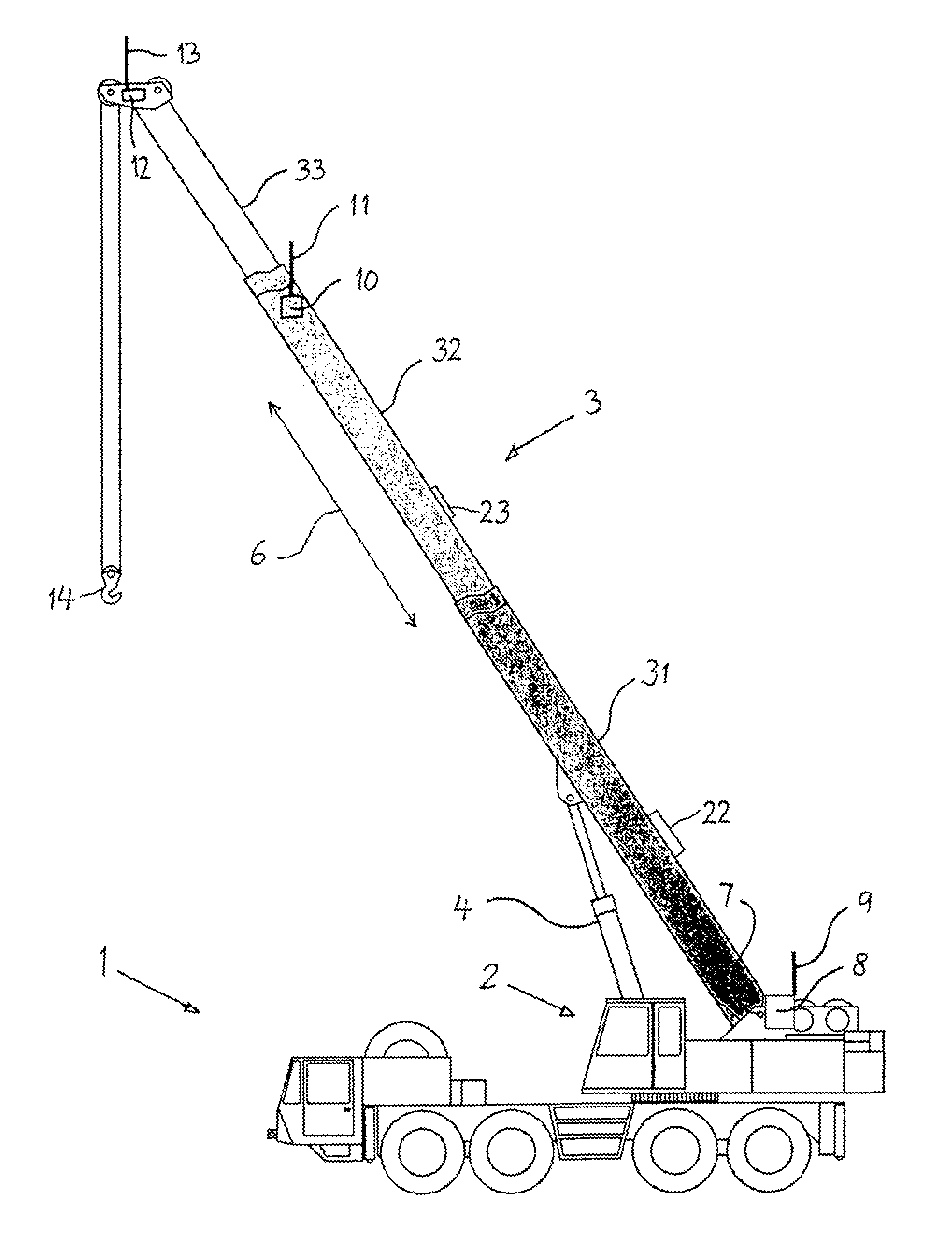
[0010]The drawing shows, in as far as shown in detail, a crane with 1 as piece of mobile equipment that comprises in a known manner a rotatable semitrailer 2 as well as a telescoping arm 3 with several telescoping parts 31, 32, and 33. The first extension arm part 31 carried directly on the rotatable semitrailer 2 is pivoted up by a hydraulic unit 4. Starting from the first extension arm part 31, middle and outer telescoping parts 32 and 33 can be telescoped in a longitudinal direction 6, that is, they are designed to be pushed into or extended out of one another. The entire telescoping arm 3 can be pivoted up by the hydraulic unit 4 about a pivot axis 7 on the rotatable semitrailer 2 and be telescoped via means not further shown. Since the invention relates to the determination of the position of the individual telescoping parts 31 to 33 relative to each other and relative to the rotatable semitrailer 2, a description of the rest of the construction of crane vehicle 1 is not necess...


PUM


Abstract

Mobile or stationary working apparatus, in particular a working vehicle, with at least one telescopic extension arm (3) which has two or more extension arm elements (31, 32, 33) which can be moved in relation to one another, with detection means being provided on the extension arm elements (31, 32, 33) and also on a base station, in particular a rotatable trailer of the working vehicle, for detecting the position of the extension arm elements (31, 32, 33) in relation to one another and with respect to the base station, with provision being made, according to the invention, for the detection means to be in the form of radio detection means, with a radio base unit (8) being arranged on the base station and further transponder units (10, 12) being arranged on the extension arm elements (32, 33).

Description

CROSS REFERENCE TO RELATED APPLICATIONS[0001]This application is the US national stage of PCT application PCT / DE2007 / 000890, filed 2 Feb. 2007, published 6 Dec. 2007 as WO2007 / 137634, and claiming the priority of German patent application 102006025002.8 itself filed 30 May 2006, whose entire disclosures are herewith incorporated by reference.FIELD OF THE INVENTION[0002]The invention relates to mobile or stationary equipment, especially a construction vehicle, with at least one telescoping arm comprising two or more telescoping parts that can move relative to each other, with detectors provided on the telescoping parts as is well as on a base for detecting the position of the telescoping parts relative to each other and relative to the base.STATE OF THE ART[0003]In mobile equipment, e.g. in automotive cranes, it is known that a first extension arm part is mounted on a rotatable semitrailer, can pivot vertically, and is constructed so that it can rotate together with the semitrailer. ...

Claims


Application Information

Patent Timeline
Patent Type & Authority Patents(United States)
IPC IPC(8): B66C13/18
CPCB66C13/16B66C13/44B66C13/46
Inventor MOLLER, ULRICH
Owner HIRSCHMANN AUTOMATION AND CONTROL
Why Eureka
Try Eureka