Methods and apparatus for facilitating capture of magnetic credit card data on a hand held device

a technology of magnetic credit card data and hand held devices, which is applied in the direction of digital data processing details, substation equipment, instruments, etc., can solve the problems of frustrating user experience, inaccurate location reported by the touch screen, and user having to press down with some force on the touch screen

Active Publication Date: 2012-05-22
MOVELLA INC
View PDF18 Cites 50 Cited by
  • Summary
  • Abstract
  • Description
  • Claims
  • Application Information

AI Technical Summary

Benefits of technology

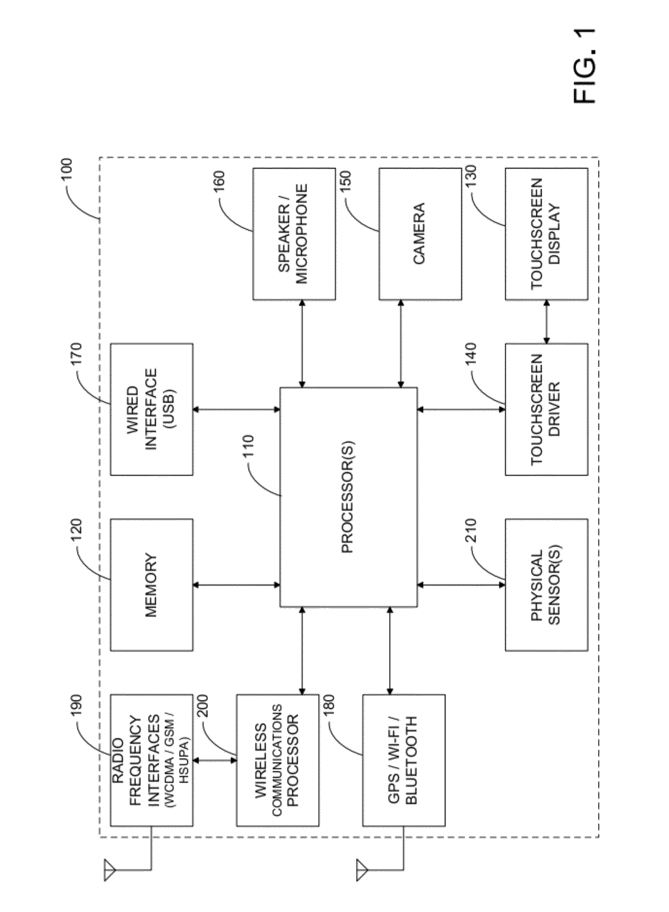
[0018]Various embodiments of the present invention disclose a computer system such as a cell phone, internet access device, media player, or the like having a touch screen display and one or more physical sensors. In operation, when a user touches a location on the touch screen display, the function associated with the touched location is determined. The function may be running of an application program, selection of a function within an application program, and the like. In various embodiments, a type and / or magnitude of movement is determined by the one or more physical sensors also in response to the user touching the touch screen display. Based upon the type and / or magnitude of movement or combinations of movements, an input parameter or value may be determined for use by the selected function. Next, the function is initiated and given the input parameter or value.
[0019]Other embodiments of the present invention disclose a computer system such as a tablet computer, a smart phone, cell phone, or the like also having a display (e.g. touch screen) and one or more physical sensors. In operation, when a user touches a location on the touch screen display, the function associated with the touched location is again determined. The function may be running of an application program, selection of a function within an application program, and the like. In various embodiments, a type and / or magnitude of movement is determined by the one or more physical sensors also in response to the user touching the touch screen display. The type and / or magnitude of movement is then compared to one or more thresholds for type and / or magnitude of movement. In various embodiments, if the threshold is not exceeded, the function is inhibited, and when the threshold is exceeded (e.g. enough physical impulse), the function is performed.
[0020]Other embodiments of the present invention disclose a computer system such as a tablet computer, a smart phone, cell phone, or the like also having a touch screen display and one or more physical sensors. In operation, when a user physically perturbs the computer system, the perturbation will cause the computer system to perform a user-desired action. The perturbation may be a change in physical position or angular orientation of the computer system, a change in air pressure, a change in sensed magnetic field, or the like. Merely as examples, a user tapping upon a case of the computer system (device) (or a surface upon which the computer system is laying upon or may cause the computer system to take a picture; start or stop a timer; answer or disconnect a telephone call; invoke an application (e.g. knock-knocking on a computer system to invoke a VOIP application, a chat application, an IM, or the like); or the like. As other examples, a user positioning a credit card magnetic strip near the computer system may invoke a payment application and / or may cause the computer system to sense the data encoded on the magnetic strip; a sudden change in magnetic field may cause the computer system to shut down; a constant or sudden change in air pressure may invoke a pressure monitoring program (e.g. a scuba diving log application, a weather application); may cause the computer system to disconnect wireless transceivers and enter an “airplane mode;” or the like.
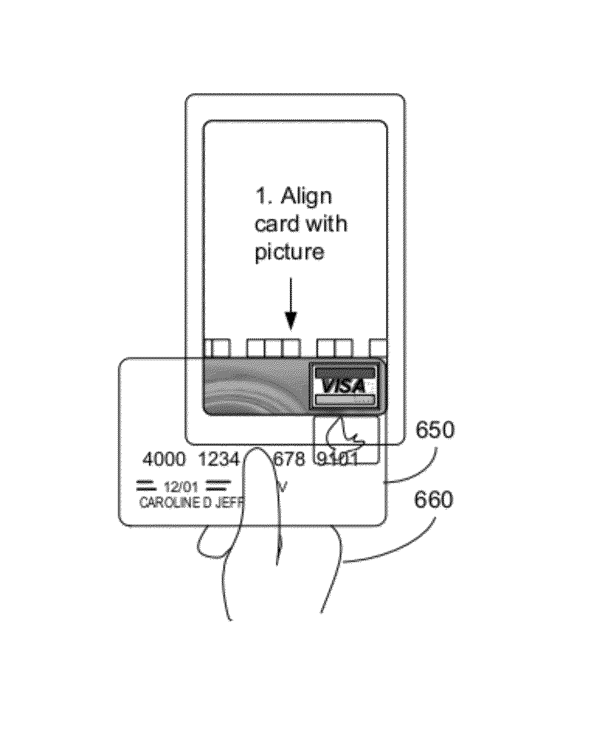
[0021]According to one aspect of the invention, a computer implemented method for processing data stored on a magnetic stripe of a user provided medium performed by a hand-held computer system programmed to perform the method is described. One process includes displaying, with a processor disposed within the computer system, a first alignment graphical user interface on a display of the computer system, wherein the first alignment graphical user interface includes a first visual alignment mark, wherein the first alignment mark is positioned on the display relative to a position of a MEMS magnetic field sensor disposed within the computer system at a first offset, wherein when a user aligns the user provided medium to the first alignment mark on the display, a portion of a first track of the magnetic stripe is disposed above the MEMS magnetic field sensor. A method may include sensing, by the MEMS magnetic field sensor, a plurality of magnetic data stored on the first track of the magnetic stripe, in response to the user aligning the user provided medium to the first alignment mark, and moving the user provided medium along the first alignment mark, and determining, with the processor, a plurality of user data stored on the first track of the magnetic stripe in response to the plurality of magnetic data stored on the first track.
[0022]According to yet another aspect of the invention, a hand-held computer system for processing data stored on a magnetic stripe of a user provided medium is disclosed. One apparatus may include a housing and a tangible memory for storing a plurality of non-transitory executable instructions. A device may include a display disposed within the housing, wherein the display is configured to display a plurality of graphical user interfaces to a user, and a MEMS magnetic field sensor disposed within the housing, wherein the MEMS magnetic field sensor is configured to sense magnetic data stored within a magnetic stripe of the user provided medium. A system may include a processor disposed within the housing and coupled to the tangible memory, the display, and to the MEMS magnetic field sensor, wherein the processor is programmed to perform a plurality of functions by the plurality of non-transitory executable instructions. In various embodiments, the plurality of non-transitory executable instructions may include executable code that programs the processor to display a first alignment graphical user interface on the display, wherein the first alignment graphical user interface includes a first visual alignment mark, wherein the first alignment mark is positioned on the display relative to a position of the MEMS magnetic field sensor at a first offset, wherein when the user aligns the user provided medium to the first alignment mark on the display, a portion of a first track of the magnetic stripe is sensed by the MEMS magnetic field sensor, and executable code that programs the processor to determine a plurality of user data stored on the first track of the magnetic stripe, in response to magnetic data stored within the first track of the magnetic stripe sensed by the MEMS magnetic field sensor when the user moves the user provided medium along the first alignment mark.
[0023]Various additional objects, features and advantages of the present invention can be more fully appreciated with reference to the detailed description and accompanying drawings that follow.

Problems solved by technology

Drawbacks to touch screen devices incorporating resistive-based sensors, determined by the inventor, include that if a user inadvertently touches two locations on the touch screen at the same time, the location reported by the touch screen is often incorrect.
Another drawback includes that the user has to press down with some force on the touch screen before the touch screen can detect the user touch.
This is particularly frustrating, for example, when a user is trying to touch-type using a virtual keyboard to input text.
In such cases, as the user hovers her fingers over the home row of the virtual keyboard, often her little finger, middle finger, or the like may accidentally touch the surface of the display.
These touches are then incorrectly sensed as presses of the virtual keys causing typographical errors.
Although many touch screen devices include automatic spelling / prediction software to attempt to reduce the effect of typographic errors, in many instances the predicted word is not the word the user wants.
These types of interruptions greatly interfere with the text-entry efficiency provided by the user's ability to touch-type.
Additional drawbacks determined by the inventor of resistive and capacitive based touch screen include that the sensed touches are typically binary in nature, i.e. either the finger is not touching or the finger is touching.
These types of devices cannot sense the force with which a user touches the touch screen display.
From a user point of view, these touch screen devices also do not provide a user with any sensation of pressing a button or key, i.e. they provide no tactile feedback.
Drawbacks to such approaches, determined by the inventor, include that such devices were limited to the physical performance of the micro sensors.
For example, a user could not type very quickly with such an approach because the user had to pause between key presses to wait until the micro sensors could fully reset before she could press the next key.
Further, if the user placed two or more fingers on the touch screen at the same time she depressed the touch screen (activating the micro sensor(s)), it would be unclear which touch screen location or finger the user intended.
Drawbacks to having physical buttons for such devices included that it increased manufacturing and assembly costs, increased the number of components and complexity of the devices, increased the number of potential faulty components (e.g. broken switch, dust), and the like.
Other drawbacks included that physical buttons are now often deemed to be undesirable as they decrease the aesthetics of such devices.
As merely an example, with popular devices, it is now virtually impossible for a user to enter a telephone number without requiring a user to look at the display.

Method used


Image

  • Methods and apparatus for facilitating capture of magnetic credit card data on a hand held device
  • Methods and apparatus for facilitating capture of magnetic credit card data on a hand held device
  • Methods and apparatus for facilitating capture of magnetic credit card data on a hand held device

Examples


Embodiment Construction

[0030]FIG. 1 illustrates a functional block diagram of various embodiments of the present invention. In FIG. 1, a computing device 100 typically includes an applications processor 110, memory 120, a touch screen display 130 and driver 140, an image acquisition device 150, audio input / output devices 160, and the like. Additional communications from and to computing device are typically provided by via a wired interface 170, a GPS / Wi-Fi / Bluetooth interface 180, RF interfaces 190 and driver 200, and the like. Also included in various embodiments are physical sensors 210.

[0031]In various embodiments, computing device 100 may be a hand-held computing device (e.g. Apple iPad, Apple iTouch, Dell Mini slate, Lenovo Skylight / IdeaPad, Asus EEE series, Microsoft Courier, Notion Ink Genesis, Samsung Galaxy Tab,), a portable telephone (e.g. Apple iPhone, Motorola Droid, Droid X, Google Nexus One, HTC Incredible / EVO 4G, Palm Pre series, Nokia N900), a portable computer (e.g. netbook, laptop), a m...


PUM


Abstract

A computer implemented method for processing data stored on a magnetic stripe of a user medium performed by a hand-held computer system includes displaying an alignment GUI on a display of the computer system, wherein the GUI includes a visual alignment mark on the display at a first offset relative to a MEMS magnetic field sensor in the computer system, wherein when a user aligns the user medium to the alignment mark GUI, a portion of a first track of the magnetic stripe is disposed above the MEMS magnetic field sensor, sensing, by the MEMS magnetic field sensor, magnetic data stored on the first track when the user aligns the user medium to the visual alignment mark, and moves the user medium along the visual alignment mark, and determining user data stored on the first track from the magnetic data stored on the first track.

Description

CROSS-REFERENCES TO RELATED APPLICATIONS[0001]The present application relates to and incorporates by reference, for all purposes, the following pending patent applications: U.S. patent application Ser. No. 12 / 490,067, filed Jun. 23, 2009, U.S. patent application Ser. No. 12 / 717,070, filed Mar. 3, 2009, and U.S. patent application Ser. No. 12 / 787,368, filed May 25, 2010. The present invention also incorporates by reference, for all purposes, the following pending patent applications related to magnetic field sensors: U.S. patent application Ser. No. 12 / 859,631, filed Aug. 19, 2010, U.S. Pat. App. No. 61 / 347,805, filed May 24, 2010, and U.S. Pat. App. No. 61 / 348,387, filed May 26, 2010.[0002]The present application is also related to concurrently filed U.S. patent application Ser. No. 12 / 940,023, U.S. patent application Ser. No. 12 / 940,025, and U.S. patent application Ser. No. 12 / 940,026, all of which are commonly owned and incorporated by reference for all purposes.BACKGROUND OF THE ...

Claims


Application Information

Patent Timeline
Patent Type & Authority Patents(United States)
IPC IPC(8): G06K7/08
CPCH04M1/72522G06F1/1696G06F3/0416H04M1/7253H04M2250/12G06F3/0488G06F2203/04105G06F2203/04106H04M1/72412H04M1/72403
Inventor WAN, HONGMERRILL, JR., RAYMOND
Owner MOVELLA INC
Why Eureka
Try Eureka