Multi-chip doherty amplifier with integrated power detection

a technology of integrated power detection and amplifier, which is applied in the direction of amplifiers, amplifiers with semiconductor devices/discharge tubes, amplifiers, etc., can solve the problems of saving design cost and production cost, and achieve the effect of saving design cost and production cost, and simple and less expensive manufacturing process

Active Publication Date: 2012-05-22
VIASAT INC
View PDF3 Cites 72 Cited by
  • Summary
  • Abstract
  • Description
  • Claims
  • Application Information

AI Technical Summary

Benefits of technology

[0004]In accordance with an exemplary embodiment of the present invention, a Doherty amplifier is provided for applications in radio frequency (RF), microwave, and other electronic systems. In an exemplary embodiment, a Doherty amplifier comprises a first MMIC having a first power detector, and a second MMIC having a second power detector. The first MMIC and the second MMIC are structurally identical. Furthermore, the first MMIC is configured as a carrier amplifier and the second MMIC is configured as a peaking amplifier. In the exemplary embodiment, an amplifier control bias of the carrier amplifier is a function of the power detected by the first power detector and an amplifier control bias of the peaking amplifier is a function of the power detected by the second power detector. In accordance with the exemplary embodiment, an integrated power detection bias control circuit is adaptable to provide bias for a class-AB main amplifier or a class-C auxiliary amplifier. The ability to assemble a Doherty amplifier using a single MMIC product results in a simple and less expensive manufacturing process. Furthermore, using the same MMIC design for both the class-AB main amplifier and the class-C auxiliary amplifier saves design cost and production cost.

Problems solved by technology

Furthermore, using the same MMIC design for both the class-AB main amplifier and the class-C auxiliary amplifier saves design cost and production cost.

Method used


Image

  • Multi-chip doherty amplifier with integrated power detection
  • Multi-chip doherty amplifier with integrated power detection
  • Multi-chip doherty amplifier with integrated power detection

Examples


Embodiment Construction

[0011]While exemplary embodiments are described herein in sufficient detail to enable those skilled in the art to practice the invention, it should be understood that other embodiments may be realized and that logical material, electrical, and mechanical changes may be made without departing from the spirit and scope of the invention. Thus, the following detailed description is presented for purposes of illustration only.

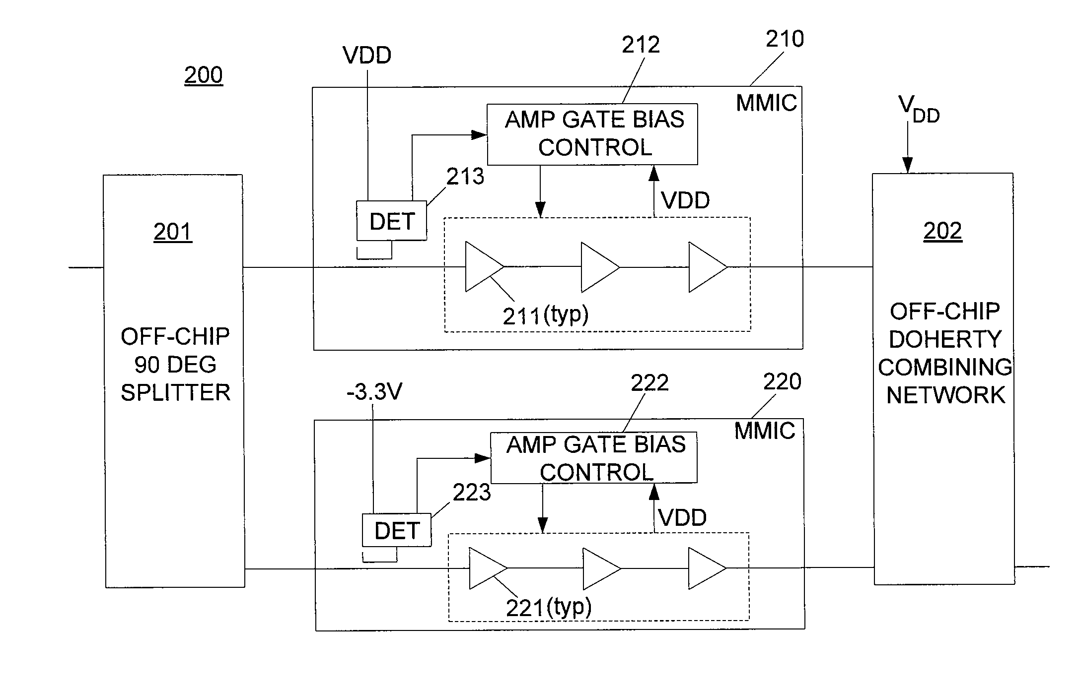
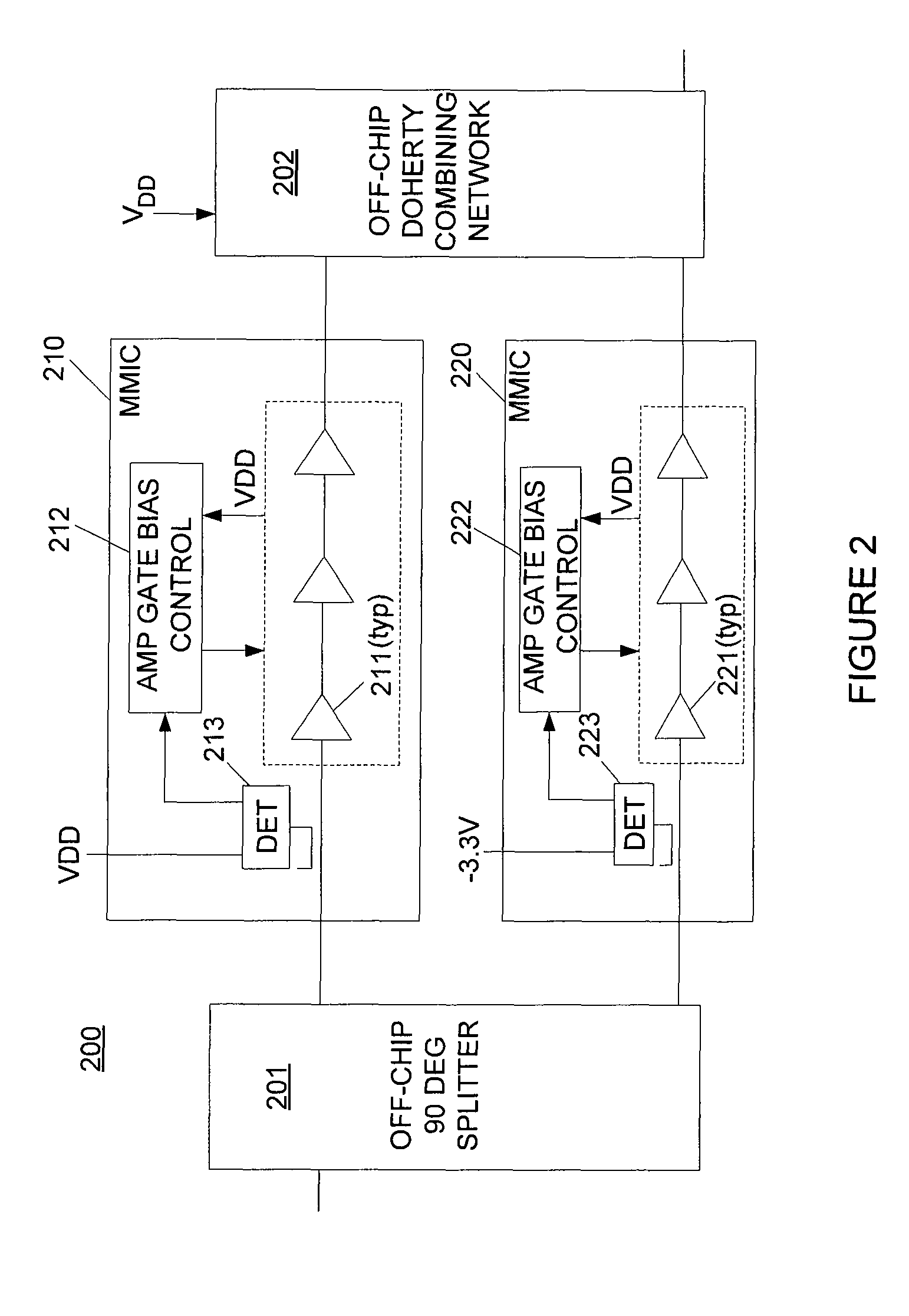
[0012]A typical Doherty amplifier includes multiple amplifier paths. The basic configuration has only two paths, a peaking amplifier path and a carrier amplifier path. In accordance with an exemplary embodiment and with reference to FIG. 2, a multi-chip Doherty amplifier 200 comprises a peaking amplifier MMIC 210 and a carrier amplifier MMIC 220. MMIC 210 and MMIC 220 each receive an input signal from an off-chip 90° splitter 201. Each MMIC 210, 220 also transmits an output signal to an off-chip Doherty combining network 202. Furthermore, in an exemplary embodiment,...


PUM


Abstract

In accordance with an exemplary embodiment of the present invention, a Doherty amplifier is provided for applications in radio frequency, microwave, and other electronic systems. An exemplary Doherty amplifier comprises a first MMIC having a first power detector, and a second MMIC having a second power detector. The first MMIC and the second MMIC are structurally identical. Furthermore, the first MMIC is configured as a carrier amplifier and the second MMIC is configured as a peaking amplifier. In the exemplary embodiment, an amplifier control bias of the carrier amplifier is a function of the power detected by the first power detector and an amplifier control bias of the peaking amplifier is a function of the power detected by the second power detector. The ability to assemble a Doherty amplifier using a single MMIC product results in a simple and less expensive manufacturing process.

Description

FIELD OF THE INVENTION[0001]The present invention relates generally to electronic amplifiers, and more specifically to employing multi-chip Doherty amplifiers with integrated power detection to control amplifier biasing.BACKGROUND OF THE INVENTION[0002]In electronics, there is an ongoing need to improve the efficiency and bandwidth of amplifier circuits. One method for improving the efficiency of an amplifier was invented in 1934 by William H. Doherty. A typical Doherty amplifier is shown in FIG. 1 and has a class-AB main amplifying stage 110 in parallel with a class-C auxiliary amplifier stage 120. The Doherty amplifier receives an input signal from an off-chip source that controls the biasing provided to the amplifier stages using a biasing control circuit. An input signal is split evenly to drive the two amplifiers, and a combining network 102 sums output signals from the main and auxiliary stages and corrects for phase differences between them. During periods of lower signal pow...

Claims


Application Information

Patent Timeline
Patent Type & Authority Patents(United States)
IPC IPC(8): H03F3/68
CPCH03F1/0261H03F1/0288
Inventor GRONDAHL, CHRISTOPHER D.
Owner VIASAT INC
Why Eureka
Try Eureka