Thermoelectric generator assembly for field process devices

a technology of process device and generator, which is applied in the manufacture/treatment of thermoelectric devices, thermoelectric device junction materials, lighting and heating apparatus, etc., can solve the problems of high power consumption of typical field instruments, over-long distance wiring of field instruments, and inability to provide power to field instruments through wireless communication loops. to achieve the effect of efficient thermoelectric power generation

Active Publication Date: 2012-05-29
ROSEMOUNT INC
View PDF207 Cites 13 Cited by
  • Summary
  • Abstract
  • Description
  • Claims
  • Application Information

AI Technical Summary

Problems solved by technology

Often, the cost of wiring a field instrument over long distances exceeds the cost of the field instrument itself.
When a wireless communication loop is used to communicate with a field instrument, the wireless communication loop does not provide a power supply to the field instrument, and separate power supply wiring is needed.
While the power required for a typical field instrument is extremely low, field instruments are often located in very hot, dangerous or inaccessible locations in the process plant.
In such locations, it may be impractical to use a chemical battery as a source of low power in a field instrument.
The environments in such locations are often dirty or shielded from sunlight, making use of solar cells for power supply impractical.
Solar cells and batteries, in the plant environment, require too much maintenance to be usable for power supply in many field instrument applications.
The amount of energy lost due to a waste heat flow often greatly exceeds the amount of electrical power required by a field instrument.
However, there are a number of practical problems that arise.

Method used


Image

  • Thermoelectric generator assembly for field process devices
  • Thermoelectric generator assembly for field process devices
  • Thermoelectric generator assembly for field process devices

Examples


Embodiment Construction

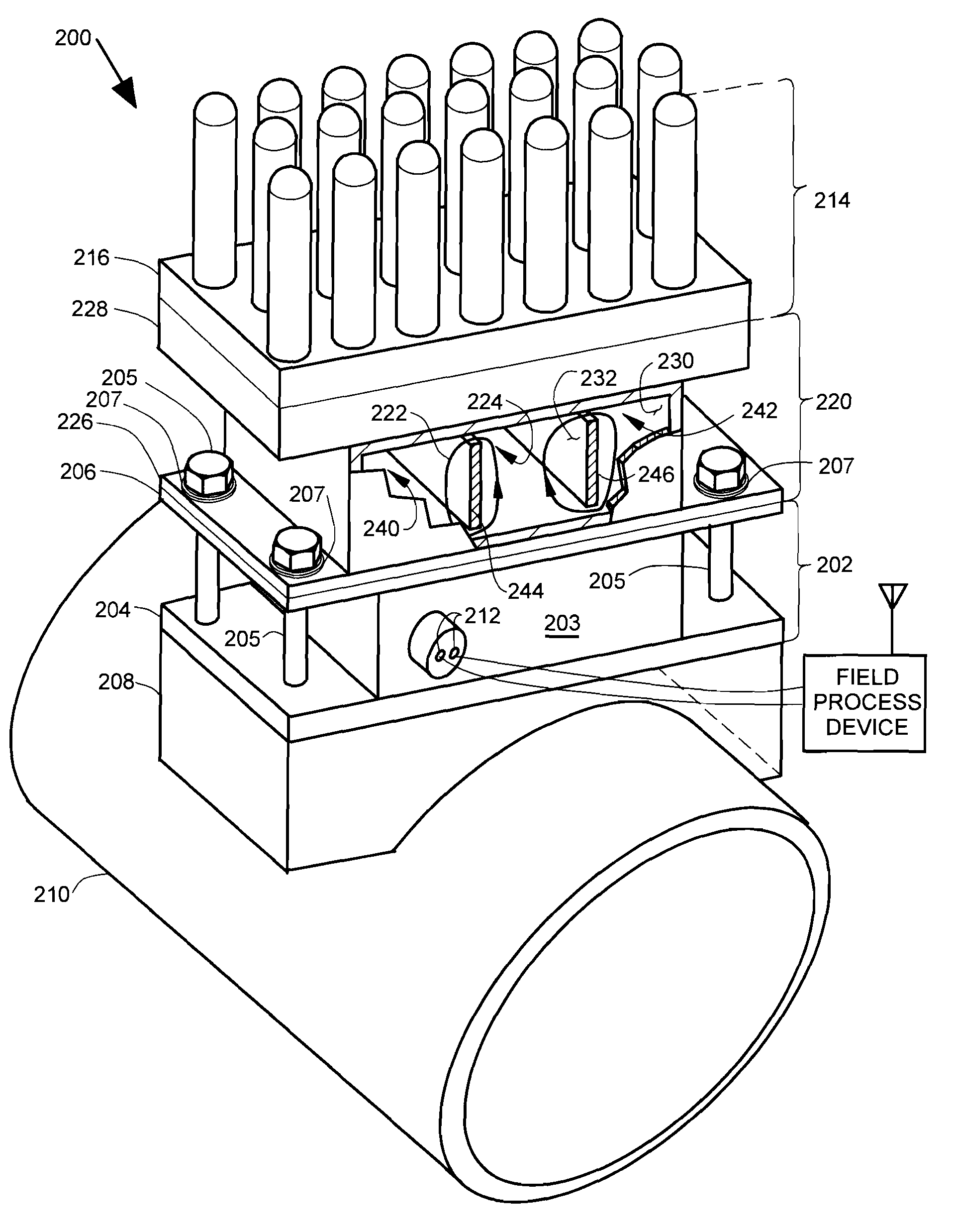
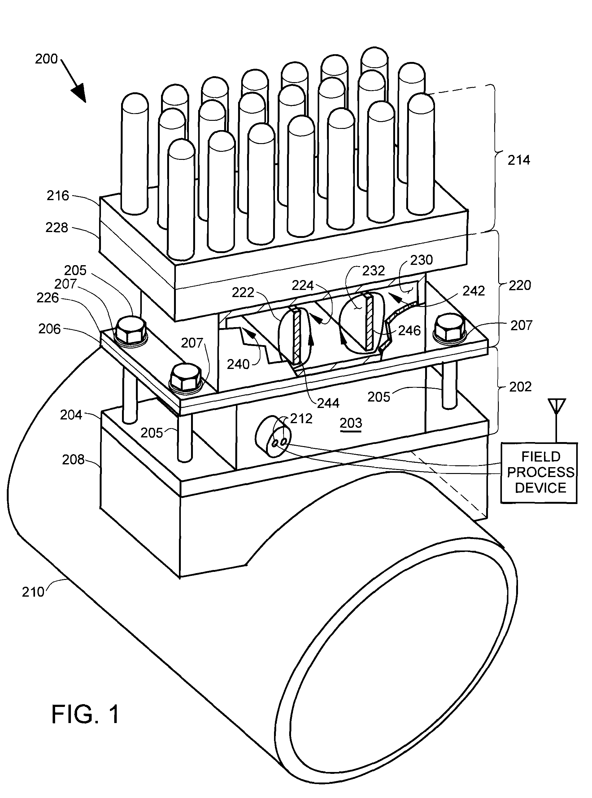
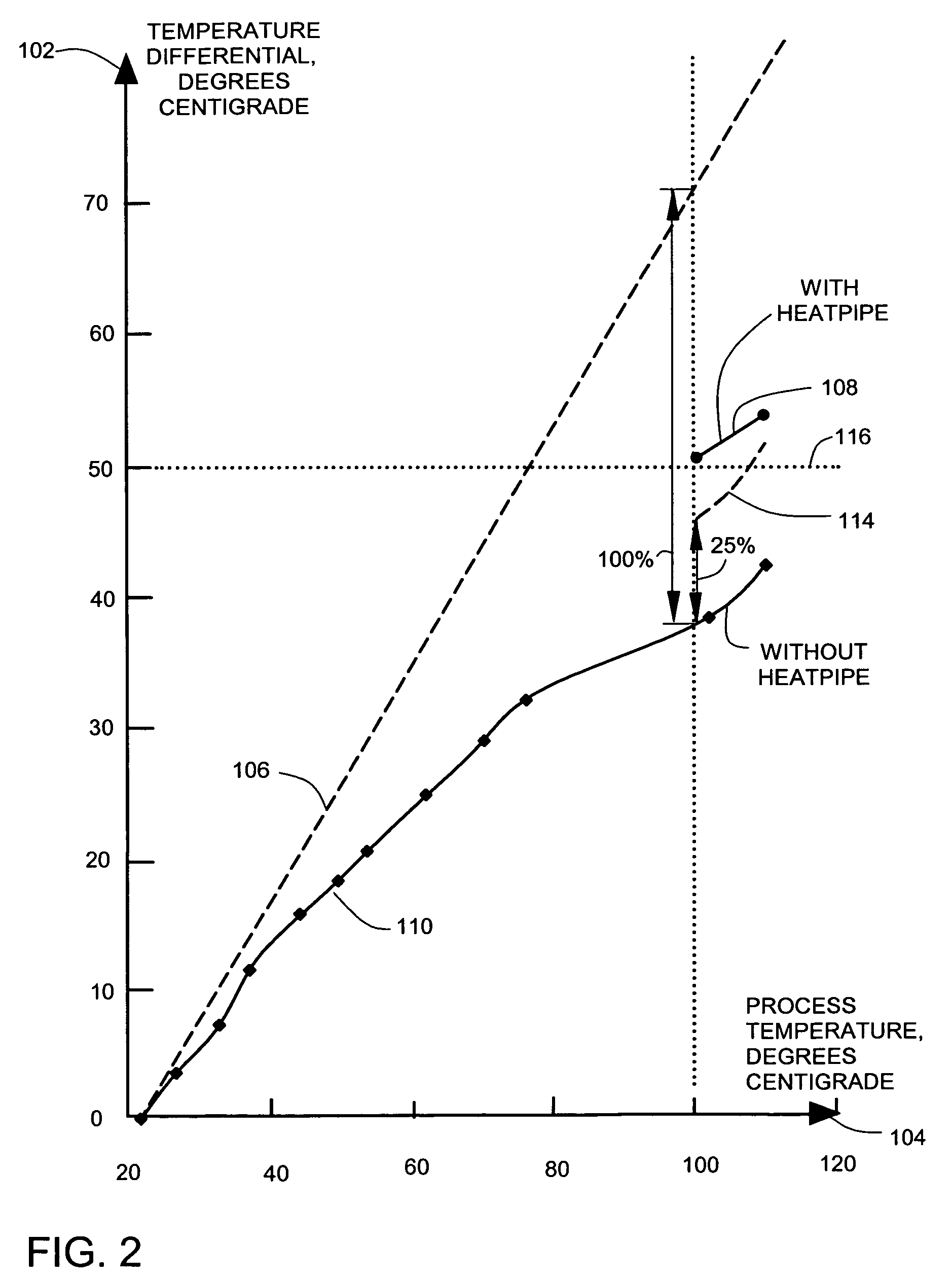
[0014]In the embodiments described below, a thermoelectric generator has a hot junction flange, or a hot junction flange adapter, that is shaped to couple to a heated process vessel such as a pipeline or a tank. The shaping of the hot junction flange provides good thermal conductance between the hot junction and the process vessel. The thermoelectric generator has a cold junction flange that is coupled to an evaporator flange of a heat pipe. A condenser flange of the heat pipe is coupled to a heat sink. The use of the heat pipe reduces the temperature of the cold junction flange, which provides an increased temperature differential between the hot junction flange and the cold junction flange. The increased temperature differential increases the voltage at a thermoelectric power output to more than 5 volts. The increased temperature differential increases the efficiency of the thermoelectric power generation. The thermoelectric power output can be used to power field process devices ...


PUM


Abstract

A thermoelectric generator assembly includes a thermoelectric generator with hot and cold junction flanges. The hot junction flange includes an adapter shaped for thermally coupling to a process vessel. The thermoelectric generator producing a thermoelectric power output. A heat sink thermally couples to ambient air and has a heat sink flange. A heat pipe assembly includes fluid in a circulation chamber. The circulation chamber has an evaporator flange mounted to the cold junction flange and a condenser flange mounted to the heat sink flange. At least a portion of the fluid transports heat from the evaporator flange to the condenser flange. When a heat pipe assembly on a cold junction flange is used with many of the types of heat flows that are available in process industries, more efficient thermoelectric power generation can be provided in the process industries.

Description

CROSS-REFERENCE TO RELATED APPLICATION[0001]Reference is made to co-pending application Ser. No. 11 / 070,860, filed Mar. 2, 2005, titled “PROCESS DEVICE WITH IMPROVED POWER GENERATION,” the content of which is hereby incorporated by reference in its entirety; and reference is also made to related co-pending U.S. patent application Ser. No. 11 / 529,780 entitled “PIPELINE THERMOELECTRIC GENERATOR ASSEMBLY,” filed Sep. 28, 2006, the contents of which are hereby incorporated by reference in their entirety.BACKGROUND OF THE INVENTION[0002]Field instruments are typically widely distributed throughout a process plant and are connected by process control loops to a control system. Field instruments typically require a supply of electrical power for operation. The electrical power can be provided by the control loops themselves or by separate power wiring to the instruments. The amount of power required by each field instrument is usually quite small, and is typically on the order of about 50 ...

Claims


Application Information

Patent Timeline
Patent Type & Authority Patents(United States)
IPC IPC(8): H01L35/00H01L35/22H01L37/00H01L35/34H01L35/30H01L35/28H01L35/14H01L35/20H01L35/02H01L35/16
CPCH01L35/30F28D15/02F28D15/025F28D15/0275H10N10/13
Inventor CHAKRABORTY, SWAPAN
Owner ROSEMOUNT INC
Why Eureka
Try Eureka