

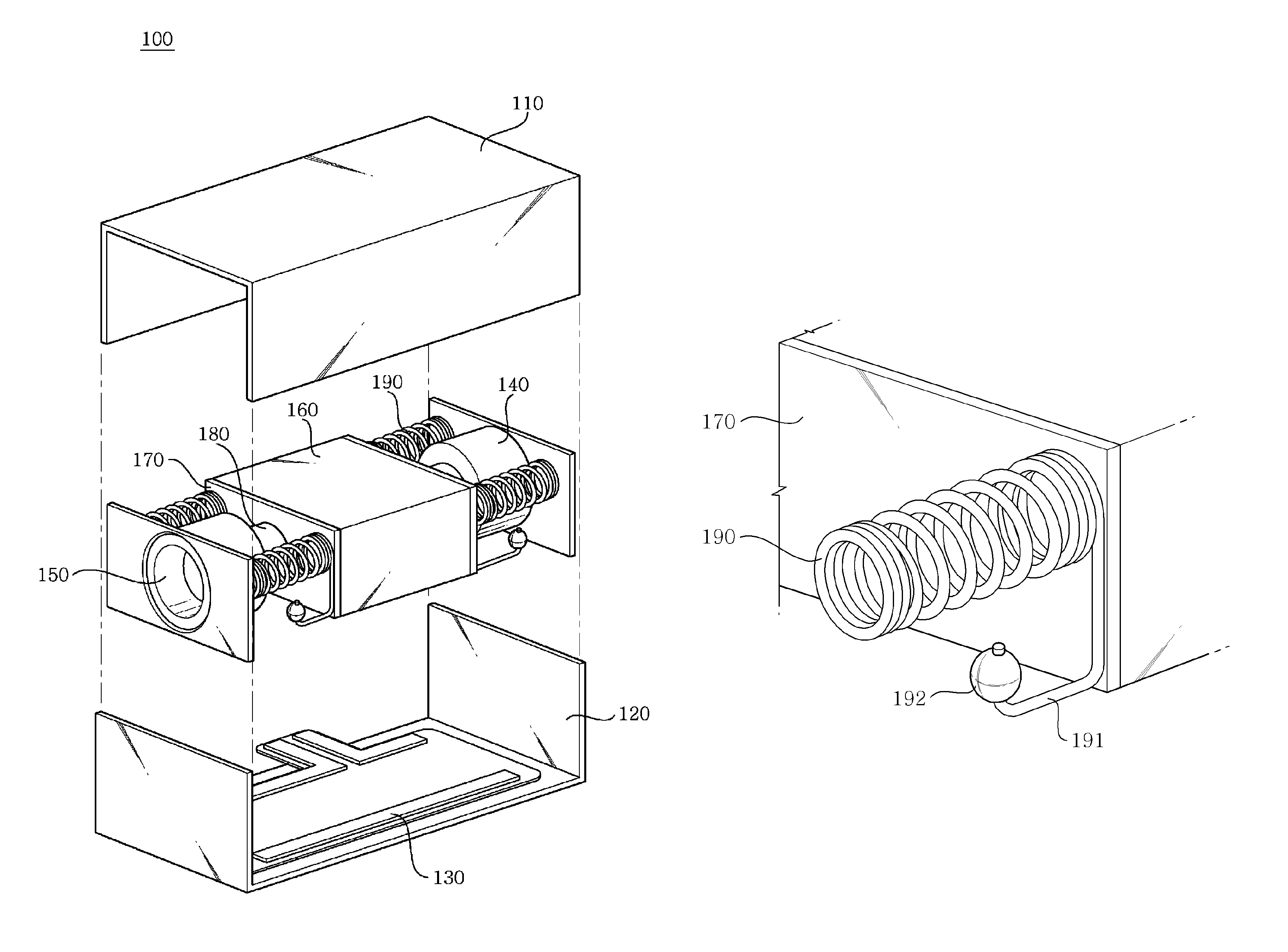
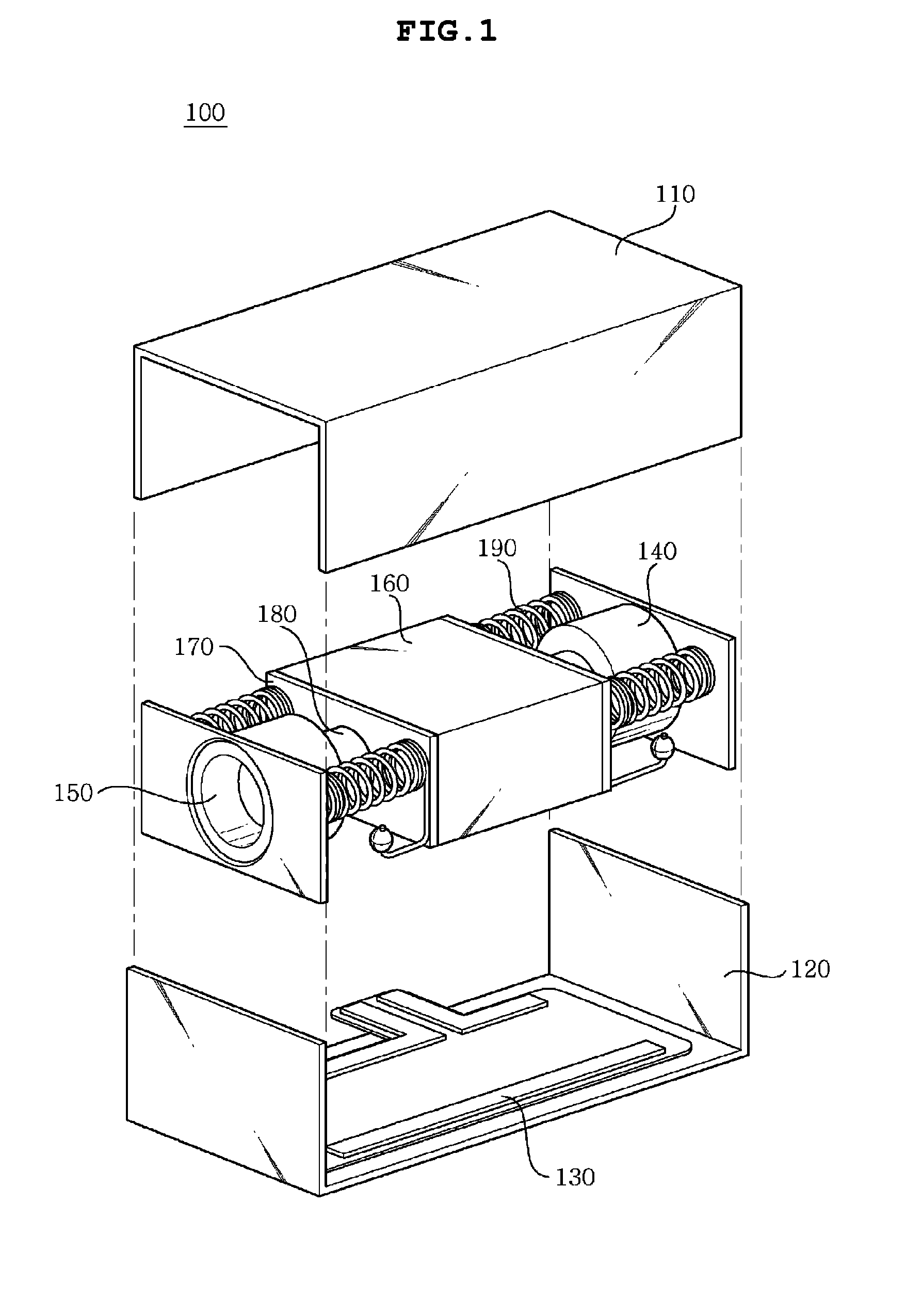
Linear vibration motor
a linear vibration and motor technology, applied in the direction of dynamo-electric machines, electrical apparatus, propulsion systems, etc., can solve the problems of short life of the motor, limited thickness of the necessary increase in vibration strength, and difficulty in realizing vibration suitable for touch screen phones, etc., to minimize friction and abrasion, and minimize noise caused by friction
- Summary
- Abstract
- Description
- Claims
- Application Information
AI Technical Summary
Benefits of technology
Problems solved by technology
Method used
Image

Examples
first embodiment
[0047]FIGS. 4 and 5 are views illustrating the ball bearing 192 according to the present invention, in which the ball bearing 192 is assembled with the extension part 191 of the spring 190. In this regard, the ball bearing 192 has the shape of a ball, thus minimizing a frictional area between the mass body 160 and the casing 110 when the mass body 160 is in operation, and preventing the abrasion of parts.
second embodiment
[0048]FIGS. 6 and 7 are views illustrating a cylinder bearing 193 according to the present invention, in which the cylinder bearing 193 is assembled with the extension part 191 of the spring 190. A stepped rail 111 is provided in a portion of a casing 110 which contacts the cylinder bearing 193, thus guiding the cylinder bearing 193 and ensuring the straightness of the mass body 120 which moves horizontally.
third embodiment
[0049]FIG. 8 is a view illustrating a ring bearing 194 according to the present invention, in which the ring bearing 194 is assembled with the extension part 191 of the spring 190.
[0050]As shown in FIGS. 4 to 8, any one of the ball bearing 192, the cylinder bearing 193, and the ring bearing 194 may be provided on the end of the extension part 191 of the spring 190.
PUM
 Abstract
Description
Claims
Application Information