DC offset correction of a radio frequency receiver used with a continuous transmission radio frequency signal

a radio frequency receiver and offset correction technology, applied in the direction of dc level restoring means or bias distort correction, amplitude demodulation, baseband system details, etc., can solve problems such as changes in dc offsets, interference with proper processing of electrical signals, and interruption of processed electrical signals

Active Publication Date: 2012-05-29
QORVO US INC
View PDF6 Cites 3 Cited by
  • Summary
  • Abstract
  • Description
  • Claims
  • Application Information

AI Technical Summary

Benefits of technology

[0006]The present invention relates to estimating a direct current (DC) offset of a radio frequency (RF) receiver when an estimated amplitude of a continuous-transmission amplitude-modulated (AM) RF signal is below a first threshold and when the RF receiver is not receiving an RF input signal. The estimated DC offset of the RF receiver may be used to improve RF receiver performance, particularly over temperature and supply voltage variations. Estimating the DC offset of the RF receiver when the estimated instantaneous amplitude of the continuous-transmission AM RF signal is below the first threshold may minimize errors in the estimated DC offset.
[0007]In one embodiment of the present invention, a DC offset of a power detection circuit is estimated when the estimated instantaneous amplitude of the continuous-transmission AM RF signal is below a second threshold. The power detection circuit may be used to estimate an average output power associated with the continuous-transmission AM RF signal. The estimated average output power may be used as part of a feedback system to regulate the average output power. The estimated DC offset of the power detection circuit may be used to improve the estimate of the average output power, particularly over temperature and supply voltage variations. Estimating the DC offset of the power detection circuit when the estimated instantaneous amplitude of the continuous-transmission AM RF signal is below the second threshold may minimize errors in the estimated DC offset.

Problems solved by technology

When the DC offsets are large enough, they may interfere with proper processing of electrical signals.
Additionally, changes in the DC offsets, such as changes that may occur over an operating temperature range or with power supply voltage variations, may be problematic.
However, in some circuits interruption of processed electrical signals may not be possible.
It may not be possible to interrupt such an RF transmit signal to make DC offset measurements of circuitry influenced by the RF transmit signal.

Method used


Image

  • DC offset correction of a radio frequency receiver used with a continuous transmission radio frequency signal
  • DC offset correction of a radio frequency receiver used with a continuous transmission radio frequency signal
  • DC offset correction of a radio frequency receiver used with a continuous transmission radio frequency signal

Examples


first embodiment

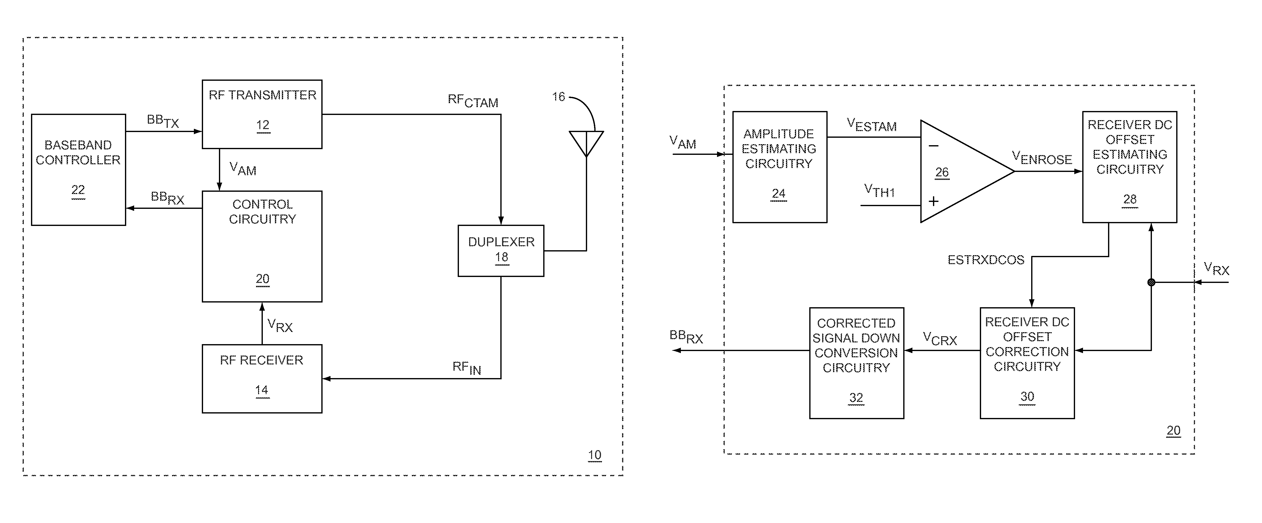
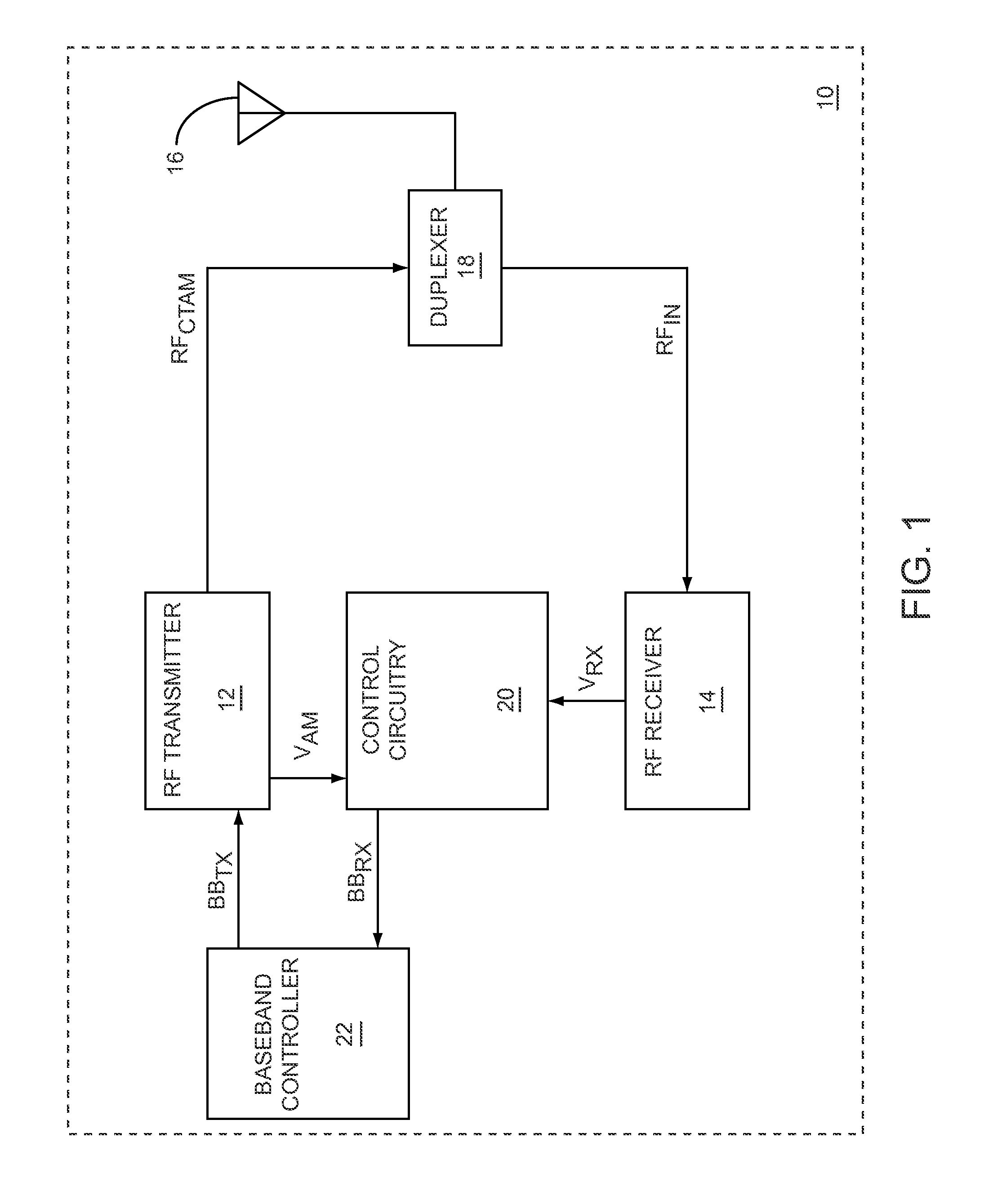
[0010]FIG. 1 shows a radio frequency (RF) communications terminal applying a correction for a receiver direct current (DC) offset to an RF input signal, according to the present invention.

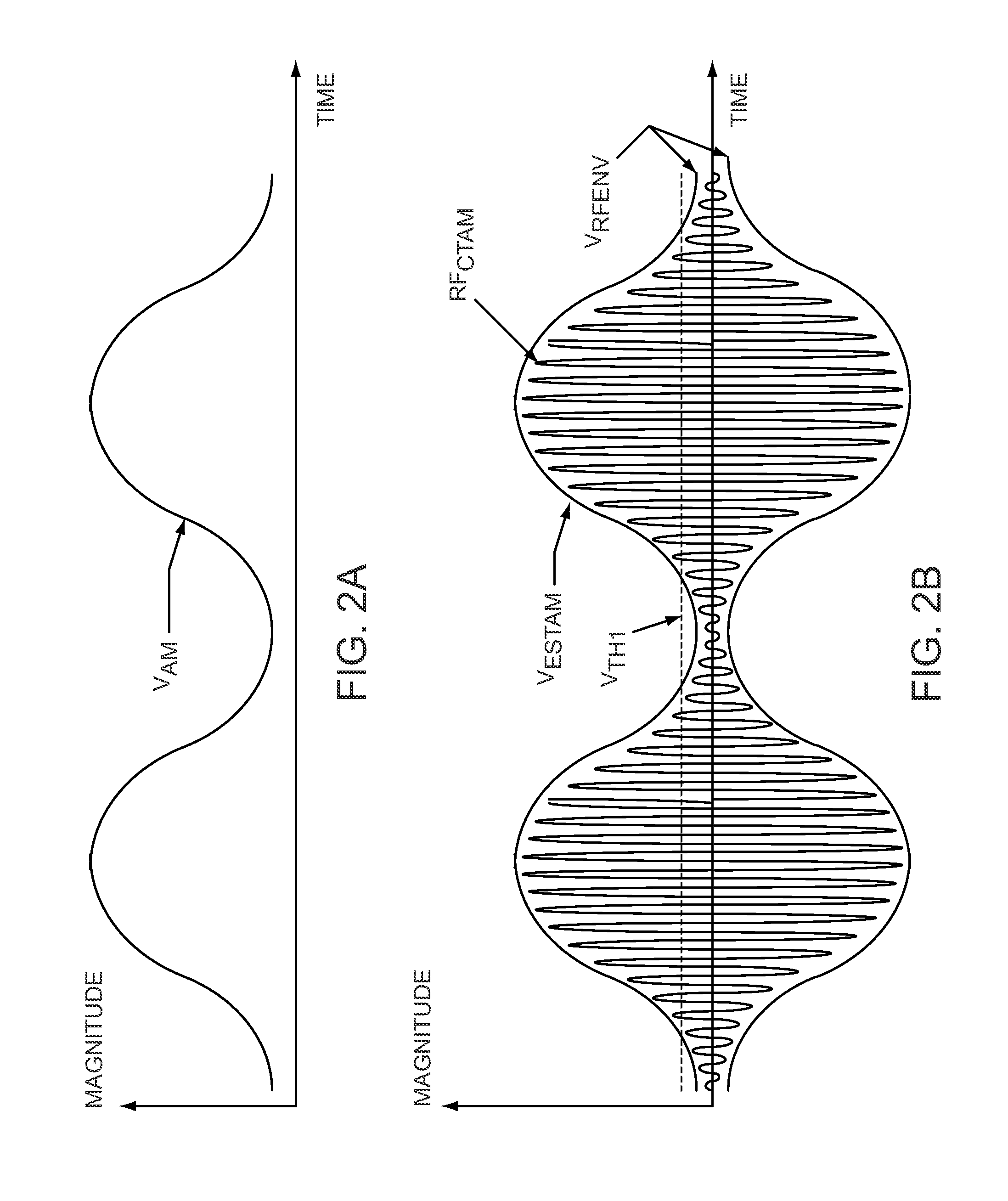
[0011]FIGS. 2A and 2B are graphs illustrating the relationships between an amplitude modulation signal, a continuous-transmission amplitude-modulated (AM) RF signal, and an estimated amplitude signal of the RF communications terminal illustrated in FIG. 1.

[0012]FIG. 3 shows details of control circuitry illustrated in FIG. 1.

second embodiment

[0013]FIG. 4 shows the RF communications terminal applying a correction for a detector DC offset to a detected output power signal, according to the present invention.

[0014]FIGS. 5A, 5B, and 5C are graphs illustrating the relationships between the amplitude modulation signal, the estimated amplitude signal, and a detected output power signal, respectively, of the RF communications terminal illustrated in FIG. 4.

[0015]FIGS. 6A and 6B are graphs illustrating the detected output power signal with a positive detector DC offset and with a negative detector DC offset, respectively, of the RF communications terminal illustrated in FIG. 4.

[0016]FIG. 7 shows details of the control circuitry illustrated in FIG. 4.

third embodiment

[0017]FIG. 8 shows the RF communications terminal applying a correction for a receiver DC offset to the RF input signal, and applying a correction for a detector DC offset to the detected output power signal, according to the present invention.

[0018]FIG. 9 is a graph illustrating the estimated amplitude signal, such that a first threshold and a second threshold are unequal, according to one embodiment of the RF communications terminal illustrated in FIG. 8.

[0019]FIG. 10 shows details of an RF receiver illustrated in FIG. 8.

[0020]FIG. 11 shows power detection circuitry of the RF communications terminal illustrated in FIG. 8 providing a temperature signal, according to one embodiment of the present invention.

[0021]FIG. 12 shows the power detection circuitry of the RF communications terminal illustrated in FIG. 8 providing a combined signal, according to an alternate embodiment of the present invention.

[0022]FIG. 13 shows details of the power detection circuitry illustrated in FIG. 12....


PUM


Abstract

The present invention relates to estimating a direct current (DC) offset of a radio frequency (RF) receiver when an estimated amplitude of a continuous-transmission amplitude-modulated (AM) RF signal is below a first threshold and when the RF receiver is not receiving an RF input signal. The estimated DC offset of the RF receiver may be used to improve RF receiver performance, particularly over temperature and supply voltage variations. Estimating the DC offset of the RF receiver when the estimated instantaneous amplitude of the continuous-transmission AM RF signal is below the first threshold may minimize errors in the estimated DC offset.

Description

[0001]This application claims the benefit of provisional patent application Ser. No. 60 / 916,890, filed May 9, 2007, the disclosure of which is hereby incorporated herein by reference in its entirety.FIELD OF THE INVENTION[0002]Embodiments of the present invention relate to direct current (DC) power detectors, radio frequency (RF) transmitters, and RF receivers, which may be used in wireless communications systems.BACKGROUND OF THE INVENTION[0003]Direct current (DC) offsets often appear in electronic circuits that process electrical signals. When the DC offsets are large enough, they may interfere with proper processing of electrical signals. Additionally, changes in the DC offsets, such as changes that may occur over an operating temperature range or with power supply voltage variations, may be problematic. One method to reduce the impact of DC offsets is to interrupt processed electrical signals and then measure and compensate for DC offsets. However, in some circuits interruption ...

Claims


Application Information

Patent Timeline
Patent Type & Authority Patents(United States)
IPC IPC(8): H04L27/02H04L27/04H04L25/06H03D1/00H04B1/38
CPCH03G3/3042H04B2001/0416
Inventor KHLAT, NADIMMYARA, DAVID
Owner QORVO US INC
Why Eureka
Try Eureka