Mechanical drive train for testing full scale compressor rigs and gas turbines

a compressor rig and drive train technology, applied in the field of gas turbines, can solve the problems of difficult to obtain partial speed mapping of compressor rigs or gas turbines, difficult to perform validation testing and mapping over the full operating range of full scale compressor rigs, and gas turbines often cannot contribute enough starting power

Active Publication Date: 2012-06-05
GENERAL ELECTRIC CO
View PDF7 Cites 19 Cited by
  • Summary
  • Abstract
  • Description
  • Claims
  • Application Information

AI Technical Summary

Benefits of technology

[0014]These and other features, aspects and advantages of the present invention will become better understood with reference to the following description and appended claims. The accompanying drawings, which are incorporated in and constitute a part of this specification, illustrate embodiments of the invention and, together with the description, serve to explain the principles of the invention.

Problems solved by technology

Due to the high shaft power demand, it is often difficult to perform validation testing and mapping over the full operating range of a full scale compressor rig.
Thus, it can be difficult to obtain partial speed mapping of a compressor rig or gas turbine because the gas turbine would either operate outside of its operability range or below the self-sustaining speed.
In addition, a gas turbine often cannot contribute enough starting power to start a compressor rig.
Furthermore, the design of a sub-scale rig usually precedes the design of the full scale counterpart, requiring dedicated resources for design, product definition and procurement.
Indeed, the need to design a sub-scale rig can add about two years to the overall design cycle of a new product.
However, such testing is limited for high power mapping because of the increased fuel flow requirements and because the turbine temperatures can exceed the limits of the turbine hardware.
Partial speed mapping using this technique also may not be achievable because the gas turbine would either operate outside its operability range or below the self-sustaining speed.
However, off frequency (partial speed) testing of a gas turbine or compressor rig cannot be performed while connected to the power grid.
Moreover, testing of a gas turbine or compressor rig at the power generation site often results in inconvenience to the power generation provider and imposes limits on the ability to redesign should the validation testing or compressor mapping reveal a potential problem with the gas turbine or compressor rig.

Method used


Image

  • Mechanical drive train for testing full scale compressor rigs and gas turbines
  • Mechanical drive train for testing full scale compressor rigs and gas turbines
  • Mechanical drive train for testing full scale compressor rigs and gas turbines

Examples


Embodiment Construction

[0020]Reference now will be made in detail to embodiments of the invention, one or more examples of which are illustrated in the drawings. Each example is provided by way of explanation of the invention, not limitation of the invention. In fact, it will be apparent to those skilled in the art that various modifications and variations can be made in the present invention without departing from the scope or spirit of the invention. For instance, features illustrated or described as part of one embodiment, can be used with another embodiment to yield a still further embodiment. Thus, it is intended that the present invention covers such modifications and variations as come within the scope of the appended claims and their equivalents.

[0021]In general, the present disclosure is directed to a system and method for testing a full scale compressor rig over a complete range of shaft speed and load conditions.

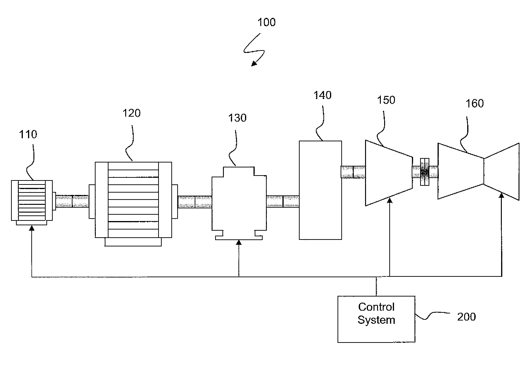
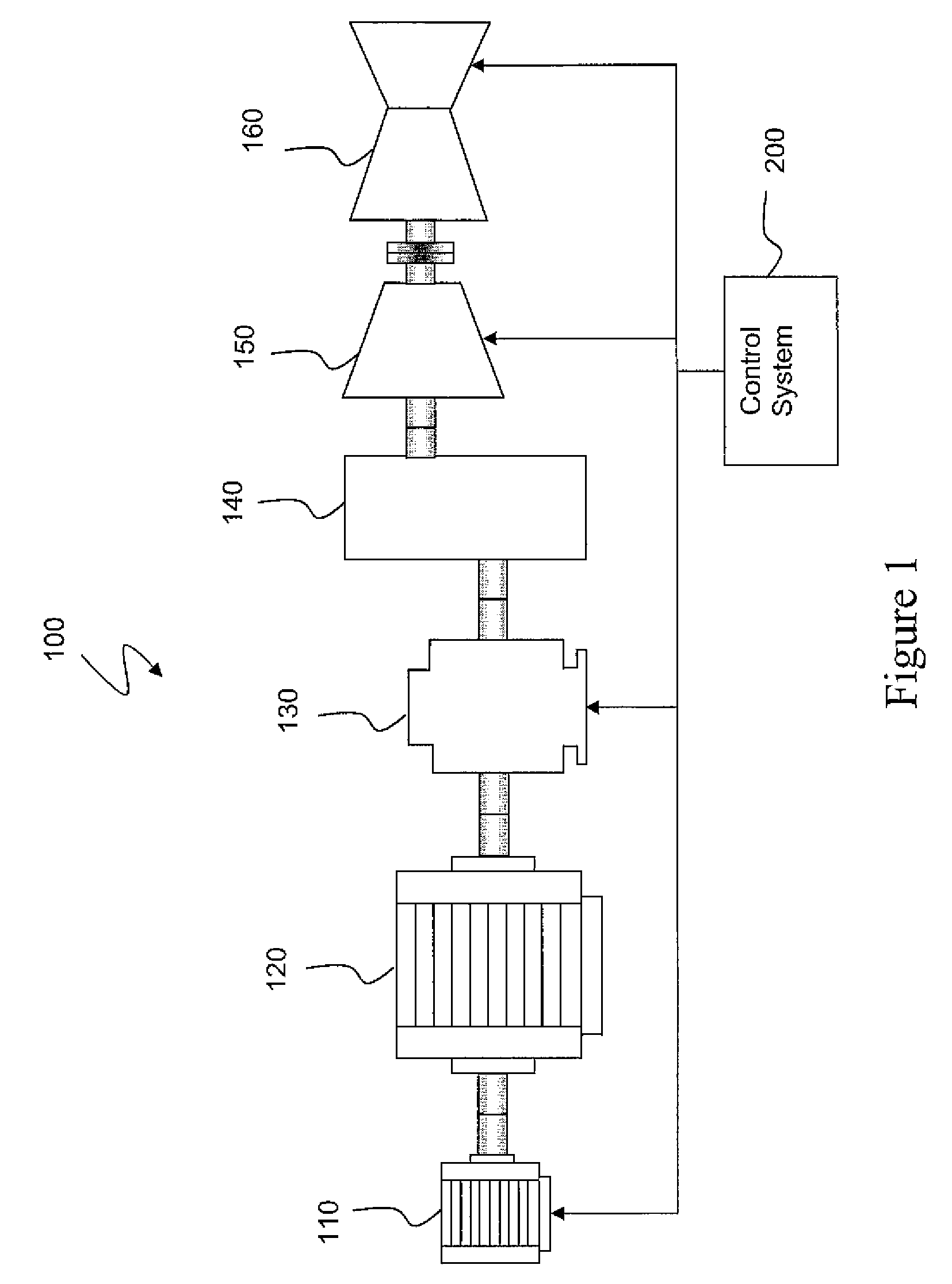
[0022]FIG. 1 provides a conceptual block diagram of a drive train 100 according to ...


PUM


Abstract

A mechanical drive train for testing a full scale compressor rig is disclosed. The drive train can include an electric motor, a gear box, and a gas turbine. The compressor rig is coupled to the drive train between the gear box and gas turbine. The drive train can further include a torque converter for transferring torque from the electric motor to the compressor rig. The drive train is configured to test a full scale compressor rig over the entire speed and load operating range, allowing for full compressor mapping from choke to stall at full load, part load (power turn down) and partial speed conditions. The drive train can also be used to test a compressor rig or gas turbine over the full range of operability for the compressor rig or gas turbine without having to connect the gas turbine to the power grid at the power generation site.

Description

FIELD OF THE INVENTION[0001]The present disclosure relates generally to gas turbines, and more particularly to a mechanical drive train assembly for testing full scale compressor rigs and gas turbines.BACKGROUND OF THE INVENTION[0002]Gas turbines are widely used in commercial operations for power generation. A gas turbine typically includes a compressor located at the front, one or more combustors around the middle, and a turbine at the rear. The compressor can include multiple stages of compressor blades attached to a rotor. Ambient air, as a working fluid, enters an inlet of the compressor, and rotation of the compressor blades progressively compresses the working fluid. The compressor can include inlet guide vanes (IGVs) and variable stator vanes (VSVs) which can be used to control the flow of ambient air into the compressor.[0003]Some of the compressed working fluid is extracted from the compressor through extraction ports for other use, and the remainder of the working fluid ex...

Claims


Application Information

Patent Timeline
Patent Type & Authority Patents(United States)
IPC IPC(8): G01M15/14
CPCG01M15/14
Inventor HANSEN, CHRISTIAN MICHAELMOODY, DOUGLAS GILESMINTO, KARL DEAN
Owner GENERAL ELECTRIC CO
Why Eureka
Try Eureka