Control device for vehicular power transmitting apparatus

a technology of control device and transmission device, which is applied in the direction of electric propulsion mounting, vehicle sub-unit features, gearing, etc., can solve the problems of prime mover suddenly stopping, normal operation disabling state, and no solution is disclosed in the patent gazette 1

Active Publication Date: 2012-06-05
TOYOTA JIDOSHA KK
View PDF7 Cites 1 Cited by
  • Summary
  • Abstract
  • Description
  • Claims
  • Application Information

AI Technical Summary

Benefits of technology

[0022]According to a seventh aspect of the present invention, the power transmitting apparatus includes the shifting portion provided in the power transmitting path and the engaging element acts as a component element of such a shifting portion. This enables the output from the prime mover to be shifted with the shifted output being transferred to the drive wheels. Thus, controlling the shifting portion allows the same advantageous effects as those of the first aspect of the present invention to be obtained.
[0023]Preferably, (a) the engaging element is actuated in response to hydraulic pressure and (b) the engaging element control is effectuated upon executing the line-pressure reduction control, operative to decrease the line pressure acting as an original pressure of working oil supplied to the engaging element, and / or the engaged-element disengaging control for operating the engaging element to a disengaging i.e. releasing side. With such controls, the engaging element control can be easily performed upon executing the hydraulic pressure control.
[0024]Preferably, further, (a) the power transmitting apparatus includes the line pressure regulator valve operative to regulate the line pressure and (b) the line-pressure reduction control represents a control for causing the line pressure regulator valve to decrease the line pressure. With such an arrangement, slightly controlling hydraulic pressure equipment, i.e. controlling the line pressure regulator valve in the presence of plural engaging elements allows all of the engaging elements, supplied with the line pressure, to be operated in disengagements.
[0025]Preferably, furthermore, (a) the power transmitting apparatus includes a line pressure generating device for generating the line pressure and (b) the line pressure control is to stop the line pressure generating device or to control the same in a direction to stop the same.
[0026]Preferably, moreover, (a) the power transmitting apparatus includes a hydraulic pressure switching valve operative to be switched in conjunction with the shift lever in accordance with an electrical command signal based on the operation of the shift lever and (b) the line-pressure reduction control is to perform a control so as to prevent the hydraulic pressure switching valve from operating with the shift lever in an interlocking relationship and to interrupt the line pressure being delivered to the engaging element or to perform a control in a direction for interruption. With such an arrangement, with plural engaging elements being provided, merely controlling the hydraulic pressure switching valve allows the all of the engaging elements, to which the line pressure is supplied, to be operated in engagements.
[0027]Preferably, further, (a) the power transmitting apparatus includes a hydraulic pressure control valve operative to reduce the line pressure for supply to the engaging element and (b) the engaged-element disengaging control is effectuated upon causing the hydraulic pressure control valve to decrease the hydraulic pressure being delivered to the engaging element. With such a control, no line pressure is caused to decrease during the engaging element control and the line pressure is already established when the engaging element control is completed, thereby making it easy to perform a control for recovery from the engaging element control.

Problems solved by technology

With a control device for such a hybrid vehicle power transmitting apparatus, a normal-operation disabling state may be caused in some cases, i.e., a failure occurs in either one of the first and second shifting portions.
However, if such a failure or the like occurs, then the prime mover may be caused to suddenly stop during the running of the vehicle propelled by the prime mover as the drive-force source.
In addition, no solution is disclosed in Patent Gazette 1 for addressing such an issue arising when the prime mover is caused to suddenly stop.

Method used


Image

  • Control device for vehicular power transmitting apparatus
  • Control device for vehicular power transmitting apparatus
  • Control device for vehicular power transmitting apparatus

Examples


Embodiment Construction

[0041]Now, an embodiment of the present invention will be described below with reference to accompanying drawings.

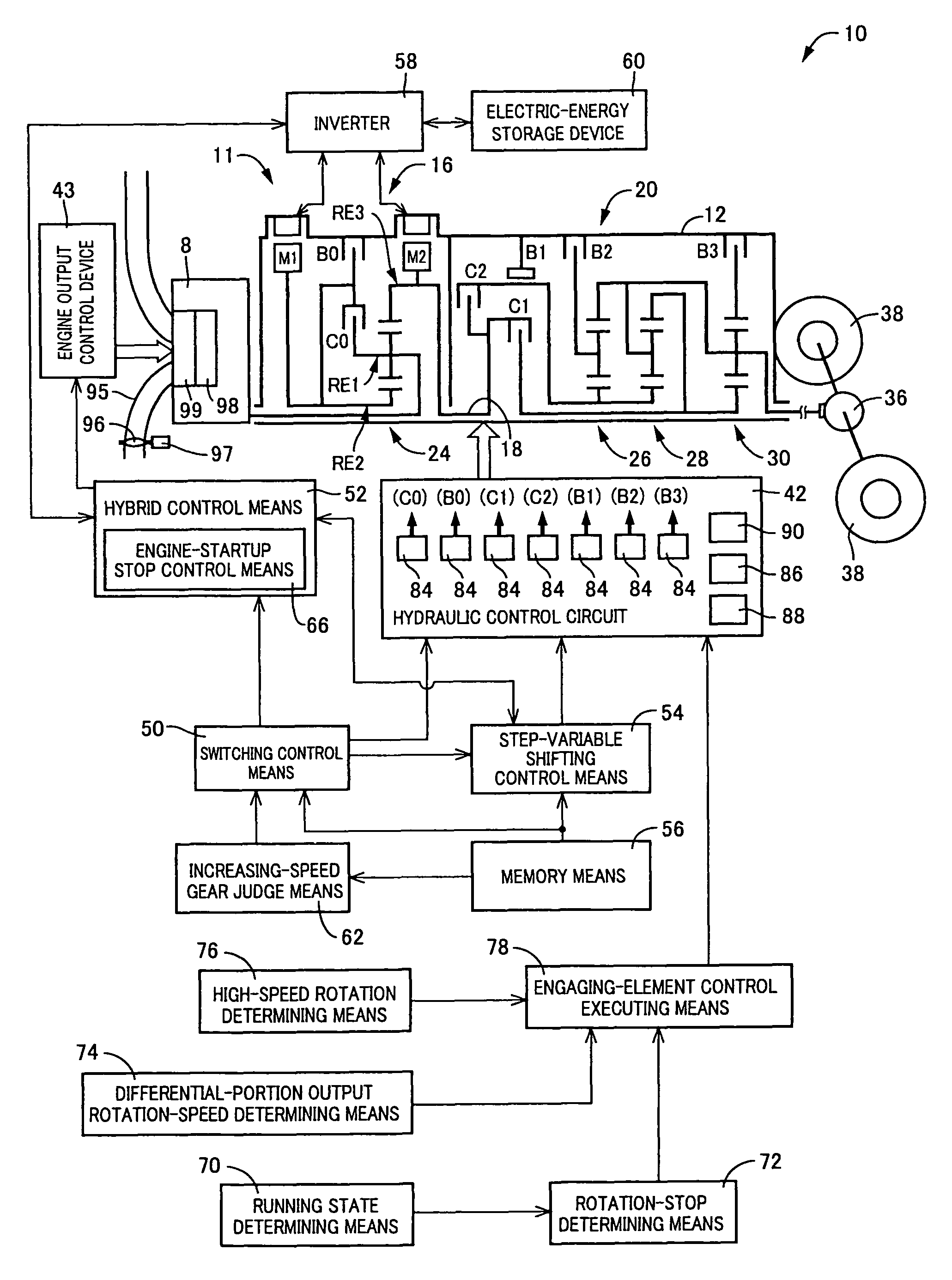
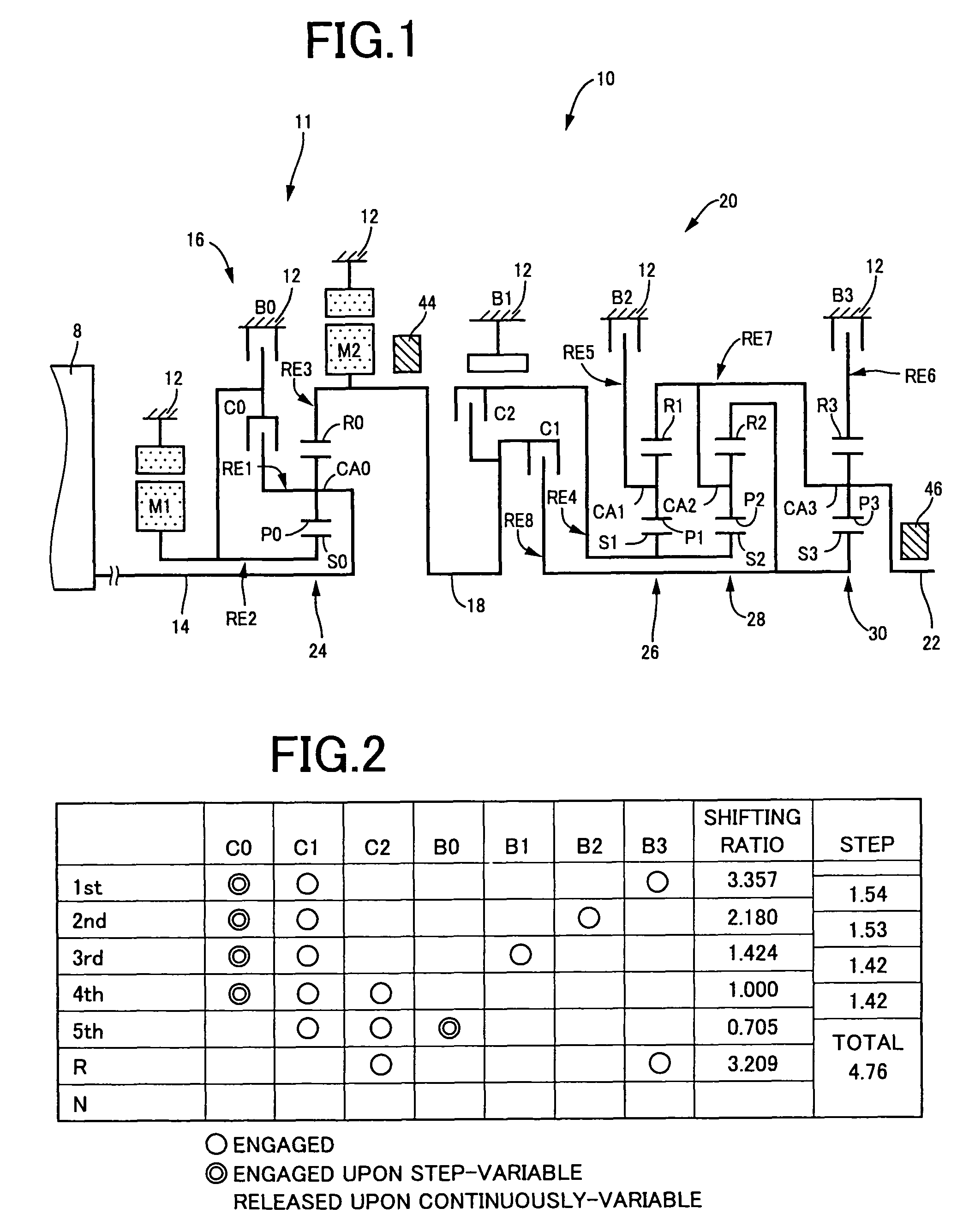
[0042]FIG. 1 is a skeleton view illustrating a shifting mechanism 10, a power transmitting apparatus for a hybrid vehicle, to which a control device of one embodiment according to the present invention is applied. As shown in FIG. 1, the shifting mechanism 10 includes an input shaft 14 serving as an input rotary member, a differential portion 11 directly connected to the input shaft 14 or indirectly connected thereto through a pulsation absorbing damper (vibration damping device) not shown, an automatic shifting portion 20 directly connected to the differential portion 11 via a power transmitting member 18 (corresponding to an output shaft of the differential portion 11) in series through a power transmitting path between the differential mechanism 11 and drive wheels 38 (see FIG. 6), and an output shaft 22 connected to the automatic shifting portion 20, all of which are...


PUM


Abstract

Rotation-stop determining portion queries as to whether the first rotary element is lowered in a rotation speed to be stopped during an engine drive mode. If the answer is YES and differential-portion rotation speed determining portion makes a positive determination, then engaging-element control-executing portion executes engaging element control. This allows a third rotary element of the differential portion, connected to drive wheels via an engaging element of an automatic shifting portion, to approach a state available to freewheel. This prevents a second rotary element and a first electric motor from reaching high-speed rotations caused by a decrease in rotation speed of the first rotary element in a stop direction and a differential action of the differential portion. This enables the prevention of a durability decrease of a power distributing mechanism and the first electric motor.

Description

TECHNICAL FIELD[0001]The present invention relates to a control devices for vehicular power transmitting apparatus. In particular, in the vehicular power transmitting apparatus, a differential portion is connected to a prime mover and operative to perform a differential action. The control device prevents a rotary element of the differential portion from reaching a high-speed rotation to thereby suppress a durability decrease of the differential portion and related component thereto.BACKGROUND ART[0002]In the related art, there has heretofore been known a hybrid vehicular power transmitting apparatus including a first shifting portion and a second shifting portion. The first shifting portion acts as a differential portion connected to a prime mover, such as an internal combustion engine or the like, to be operative to perform a differential action. The second shifting portion acts as an automatic shifting portion forming part of a power transmitting path extending from the first shi...

Claims


Application Information

Patent Timeline
Patent Type & Authority Patents(United States)
IPC IPC(8): B60W10/04F16H15/38F16H61/664F16H31/00B60K6/445B60K6/543B60K6/547B60L15/20B60L50/16B60W10/06B60W10/08B60W10/10B60W20/00F16H59/42F16H59/74F16H61/02F16H61/68F16H61/684F16H61/686
CPCB60W10/02B60W10/06B60W10/08B60W10/115B60W20/00B60K6/445B60K1/02Y10T477/606B60L2240/421B60L2240/441B60L2240/445B60L2240/485B60L2240/486B60W2510/0638B60W2510/0676B60W2510/068B60W2510/0685B60W2510/081B60W2510/1005B60W2510/107B60W2510/244B60W2520/10B60W2520/105B60W2520/28B60W2530/10B60W2540/10B60W2540/12B60W2710/0605B60W2710/081F16H2037/0873Y02T10/6286Y02T10/642Y02T10/7258Y02T10/6239B60Y2400/435Y10T477/619Y10T477/6243Y10T477/653Y10T477/688Y02T10/62Y02T10/64Y02T10/72B60W20/40B60W2710/02
Inventor KUMAZAKI, KENTAMATSUBARA, TOORUTABATA, ATSUSHIKAIFUKU, MASAKAZU
Owner TOYOTA JIDOSHA KK
Why Eureka
Try Eureka