
Virtual gateway redundancy

a virtual gateway and redundancy technology, applied in the field of satellite communication systems, can solve the problems of inefficient utilization of existing resources, lack of full utilization, idle gateway number, etc., and achieve the effect of increasing transmission power

Active Publication Date: 2012-06-05
VIASAT INC
View PDF4 Cites 36 Cited by
  • Summary
  • Abstract
  • Description
  • Claims
  • Application Information

AI Technical Summary

Benefits of technology

[0015]In one embodiment of the present invention, the second spot beam includes at least two second spot beams associated with at least two second coverage areas that are expanded upon the failure condition. Prior to expanding the at least two second coverage areas, the at least two second spot beams may be configured to utilize a common color of frequency and polarization. Upon expanding the at least two second coverage areas, the at least two second spot beams can be configured to utilize distinct colors of frequency and polarization to reduce effects of interference with one another. Under certain expansion conditions, the at least two second spot beams can use separate frequency bands and / or different polarizations.
[0017]In yet another embodiment of the present invention, the method may increase transmission power to expand the second spot beam(s).

Problems solved by technology

This create issues regarding the number of idle gateways as well as the inefficient utilization of the existing resources.
This lack of full utilization is expensive, especially considering the cost of waste physical storage space and network utilization.
When the subscriber density is low, such as in the rural or remote areas, the wired infrastructures are too costly to be deployed.
The outage could be caused by natural disasters or routine maintenance.

Method used


Image

  • Virtual gateway redundancy
  • Virtual gateway redundancy
  • Virtual gateway redundancy

Examples


Embodiment Construction

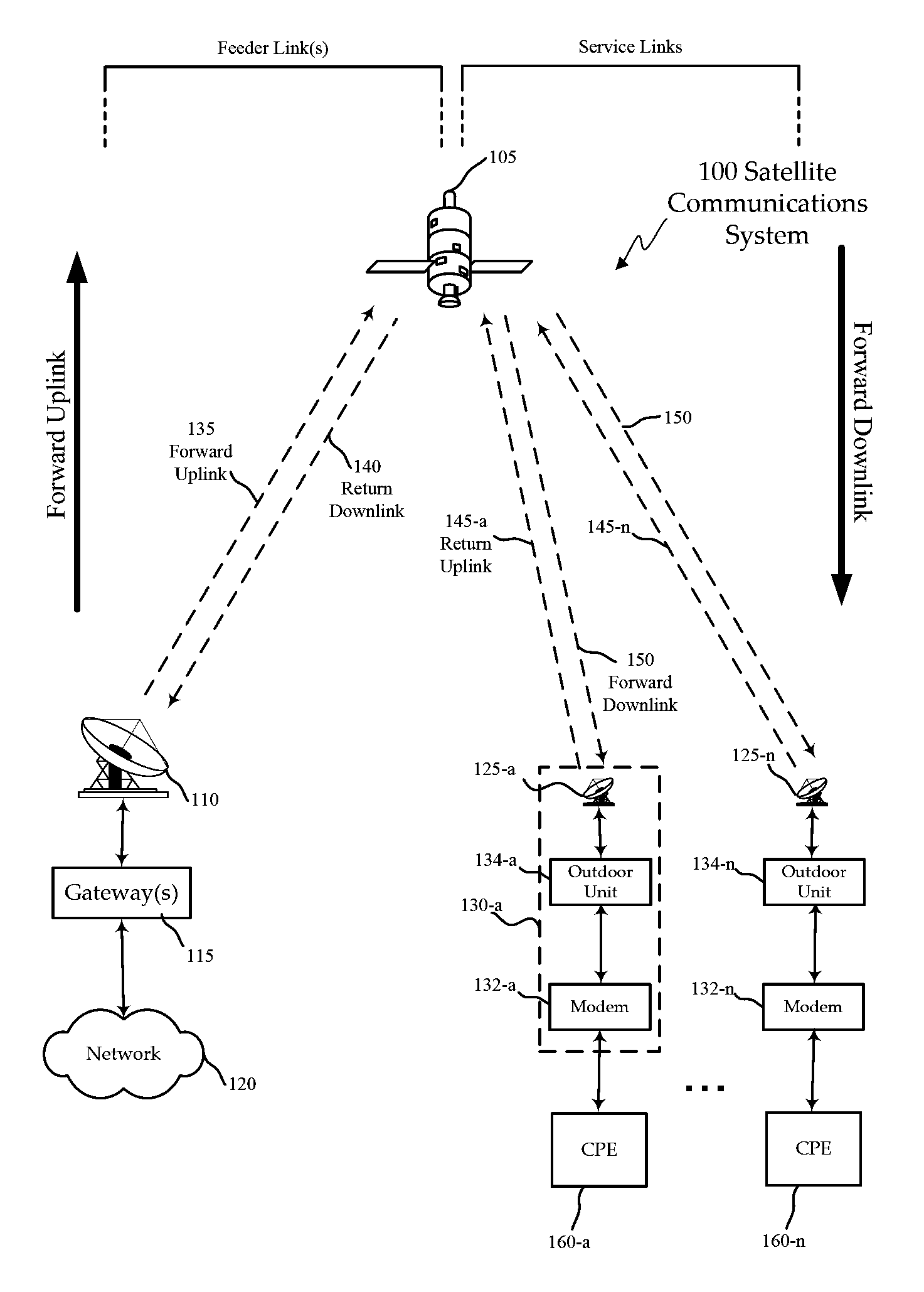
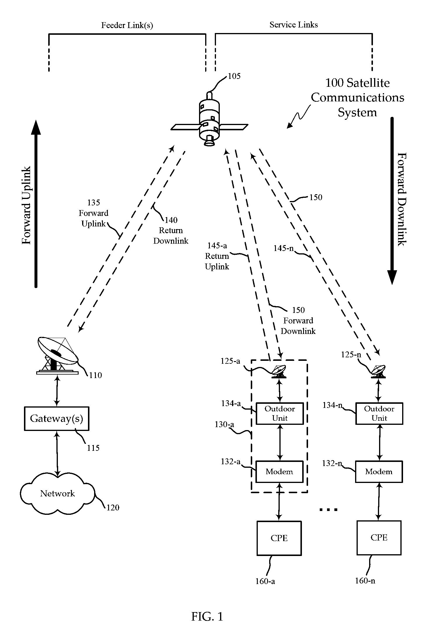
[0033]FIG. 1 shows a block diagram of an exemplary satellite communications system 100 configured according to various embodiments of the invention. The satellite communications system 100 includes a network 120, such as the Internet, interfaced with one or more gateways 115 that is configured to communicate with one or more subscriber terminals 130, via a satellite 105.

[0034]The gateway 115 is sometimes referred to as a router, switch, access node, hub, or satellite ground station and services the feeder links 135, 140 to and from the satellite 105. Although only one gateway 115 is shown, this embodiment has a number of gateways all coupled to the network 120, for example, twenty or forty gateways. The gateway 115 schedules traffic to the subscriber terminals 130, although other embodiments could perform scheduling in other parts of the satellite communication system 100.

[0035]Subscriber or user terminals 130 include an outdoor unit 134, a satellite modem 132 and an antenna 125. Al...


PUM


Abstract

A method and system are presented for providing satellite communications coverage for a geographical area involving operating a plurality of gateways including a first gateway and a second gateway, wherein the first gateway is configured to utilize at least one first spot beam associated with at least one first coverage area within the geographic area to provide relayed satellite communications to a plurality of first subscriber terminals located in the at least one first coverage area, wherein the second gateway is configured to utilize at least one second spot beam associated with at least one second coverage area within the geographic area to provide relayed satellite communications to a plurality of second subscriber terminals located in the at least one second coverage area, and upon a failure condition associated with the at least one first spot beam, expanding the at least one second coverage area to include a portion of the at least one first coverage area, to provide relayed satellite communications to at least some of the first subscriber terminals without utilizing the at least one first spot beam.

Description

CROSS-REFERENCES TO RELATED APPLICATIONS[0001]This application claims the benefit of priority to U.S. Provisional Application No. 60 / 955,026, titled “Virtual Gateway Redundancy”, filed Aug. 9, 2007, the content of which is hereby incorporated by reference for all purposes.[0002]This application incorporates by reference for all purposes U.S. Nonprovisional patent application Ser. No. 12 / 176,629 filed Jul. 21, 2008, entitled “Capacity Maximization for a Unicast Spot Beam Satellite System” .BACKGROUND OF THE INVENTION[0003]The present invention relates to satellite communication systems, and more particularly to satellite communication systems having multiple spot beams that serve as communication links between multiple coupled gateways and a plurality of subscriber terminals, wherein the satellite communication systems can provide virtual gateway redundancy without having to reserve platform resources.[0004]Telecommunications and data communications are interconnected over heterogene...

Claims


Application Information

Patent Timeline
Patent Type & Authority Patents(United States)
IPC IPC(8): H04B7/19
CPCH04B7/2041H04B7/18513
Inventor TREESH, FREDERICKMILLER, MARK J.
Owner VIASAT INC
Learn More