

Force sensor unit
a technology of force sensor and sensor, which is applied in the direction of force measurement using piezo-resistive materials, instruments, force/torque/work measurement apparatus, etc., can solve the problem of further amplifying discrepancy from the true value, and achieve more reliable differential output, accurate detection, and reliable differential output
- Summary
- Abstract
- Description
- Claims
- Application Information
AI Technical Summary
Benefits of technology
Problems solved by technology
Method used
Image

Examples
first embodiment
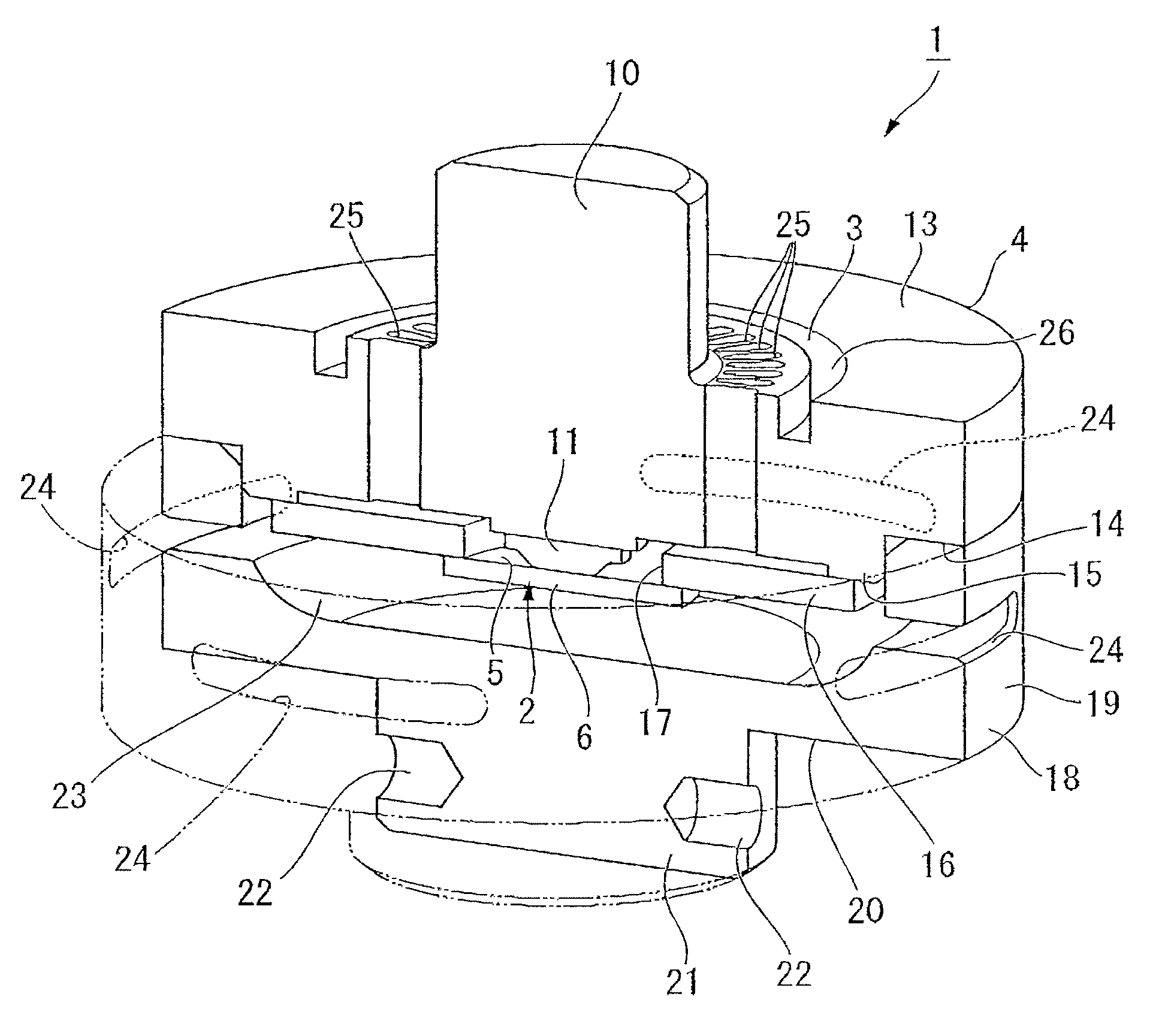
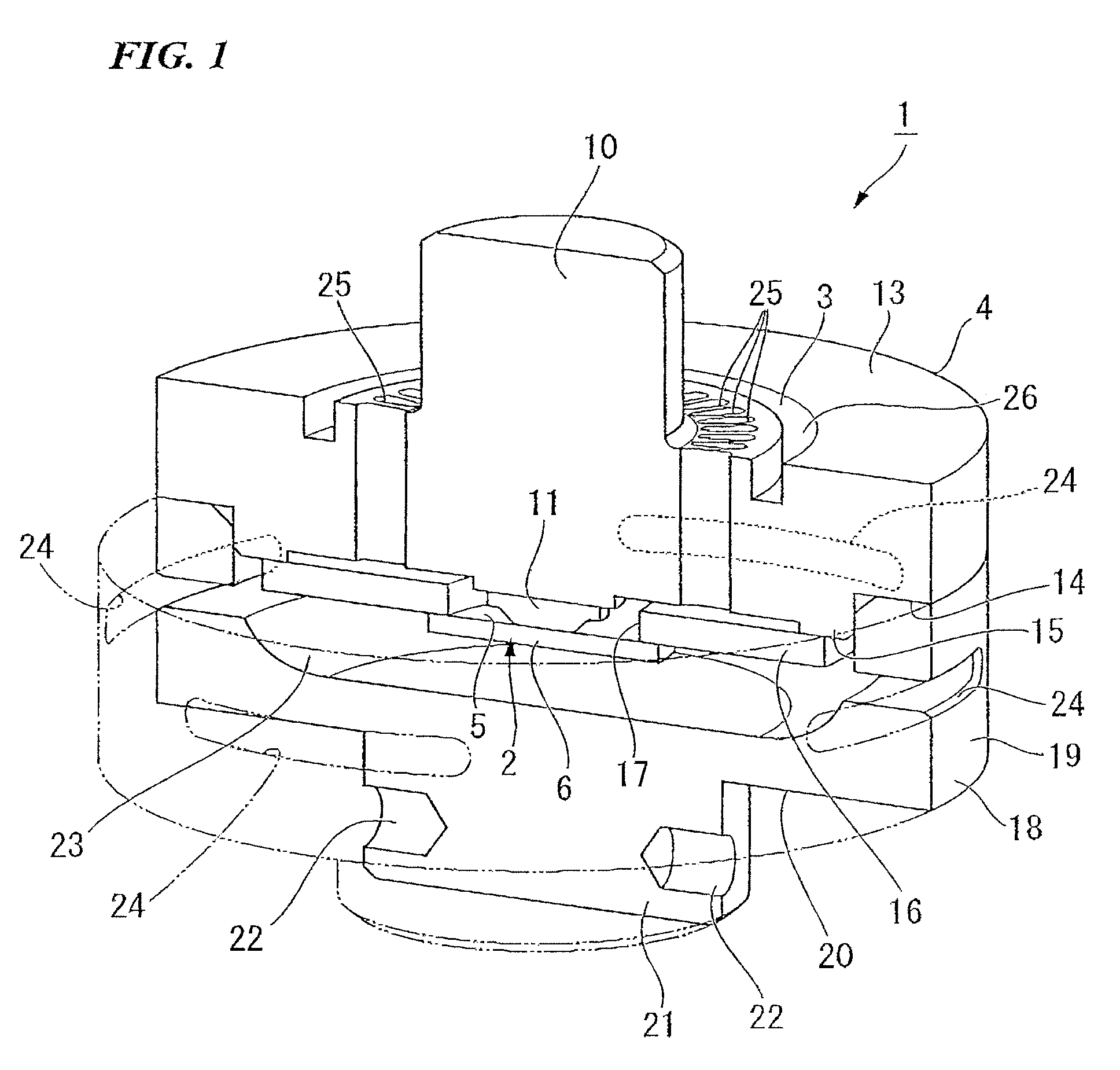
[0072]FIGS. 3 and 4 show a force sensor unit U of this invention.
[0073]The force sensor unit U is provided with two force sensors 1 and 1′ as external force detection sections.
[0074]An attenuator 4′ is provided in the force sensor unit U, and external force is dampened by this attenuator 4′ so that a dampened force is detected by the force sensor 1.
[0075]The attenuator 4′ is provided with a first housing K1 and a second housing K2.
[0076]The first housing K1 is a flat, circular cylinder-shaped component, and has a substantially level top wall 30 and a circumferential wall 31.
[0077]A step section 32 is formed in a toroidal shape on a circumferential edge of the top wall 30, and a center portion of the top wall 30 is constructed as an external force input section 33 into which external force is input.
[0078]A plurality of fan-shaped through holes 34, 34 . . . are arranged in a toroidal shape with the wider ends thereof facing outwards around the circumference of this external force inpu...
second embodiment
[0162]FIGS. 5 and 6 show a force sensor unit.
[0163]In the first embodiment, a description is given of a case in which the plurality of through holes 25 and the toroidal groove 26 are provided in the sensor fixing section 13 as the dampening mechanism section 3, however, in this embodiment, as shown in FIGS. 5 and 6, a plurality of circular through holes 55 and 56 are provided in inner diametrical side and outer diametrical side toroidal rows. Each of the circular through holes 55 on the inner diametrical side is positioned between two circular through holes 56 on the outer diametrical side which are mutually adjacent in the circumferential direction.
[0164]Because the remainder of the structure and operation of this embodiment are the same as those of the first embodiment, the same reference numerals are used for the same portions and a description thereof is omitted.
[0165]Accordingly, force can be applied to the force sensor chip 2 via the transmission section 11 without there being...
third embodiment
[0171]FIGS. 7 and 8 show a force sensor.
[0172]Specifically, the above-described circular through holes 55 and 56 are replaced by inner diametrical side arc-shaped through holes 65 and outer diametrical side arc-shaped through holes 66, and these two are placed next to each other such that the inner diametrical side arc-shaped through holes 65 are positioned between end portions of adjacent outer diametrical side arc-shaped through holes 66 in the circumferential direction.
[0173]Because the remainder of the structure and operation of this embodiment are the same as those of the first embodiment, the same reference numerals are used for the same portions and a description thereof is omitted.
[0174]Accordingly, force can be applied to the force sensor chip 2 via the transmission section 11 without there being any bias in characteristics caused by differences in the rotation direction for the moment Mz, and without there being any bias in characteristics in both the compression direction...
PUM
| Property | Measurement | Unit |
|---|---|---|
| temperature | aaaaa | aaaaa |
| temperature | aaaaa | aaaaa |
| temperature | aaaaa | aaaaa |
Abstract
Description
Claims
Application Information