Supercharge Your Innovation With Domain-Expert AI Agents!

Seal land with air injection for cavity purging

a technology of air injection and sealing land, which is applied in the direction of machines/engines, sustainable transportation, climate sustainability, etc., can solve the problems of undesirable performance restrictions, pressure barriers in the cavity that have a direct negative impact on overall engine performance, and the flow required to generate the desired pressure barrier incurs undesirable performance restrictions, so as to prevent the intrusion of hot gasses

Active Publication Date: 2012-06-19
RTX CORP
View PDF15 Cites 6 Cited by
  • Summary
  • Abstract
  • Description
  • Claims
  • Application Information

AI Technical Summary

Benefits of technology

"The patent describes a liner assembly for an exhaust liner that includes a passage for cooling air. The assembly includes a cavity where hot gases need to be prevented from flowing. Cooling air is routed into this cavity to create a barrier and prevent the intrusion of hot gases. The assembly includes a slot that is designed to vary in size to accommodate localized deviations in air flow required to create the desired barrier. The technical effect of this invention is to provide a more efficient and effective barrier to hot gases, while conserving cooling air and reducing overall consumption."

Problems solved by technology

Disadvantageously, in many instances the magnitude of by-pass flow required to generate the desired pressure barrier incurs undesirable performance restrictions.
The amount of by-pass flow required to generate the pressure barrier for the cavity has a direct negative impact on overall engine performance.

Method used


Image

  • Seal land with air injection for cavity purging
  • Seal land with air injection for cavity purging
  • Seal land with air injection for cavity purging

Examples


Embodiment Construction

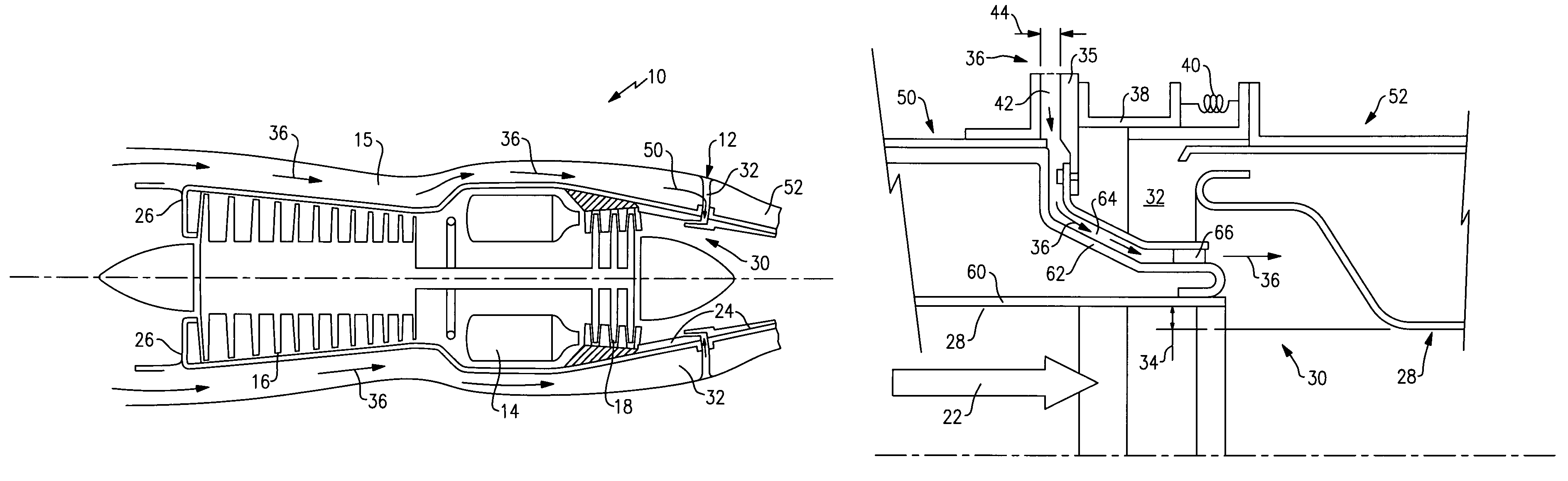
[0019]Referring to FIG. 1, an example engine assembly 10 includes an exhaust liner assembly 12. The exhaust liner assembly 12 includes an interface 30 to provide for movement of the exhaust liner 12. The engine assembly 10 is disposed within a housing 15 that includes an inner surface 26. Air enters the engine assembly 10 into a compression module 16. Compressed air from the compression module 16 is injected into a combustion module 14. In the combustion module 14, compressed air is mixed with gas and ignited to create hot core exhaust gases that are driven past a turbine module 18. Rotation of the turbine module 18 drives the compressor module 14.

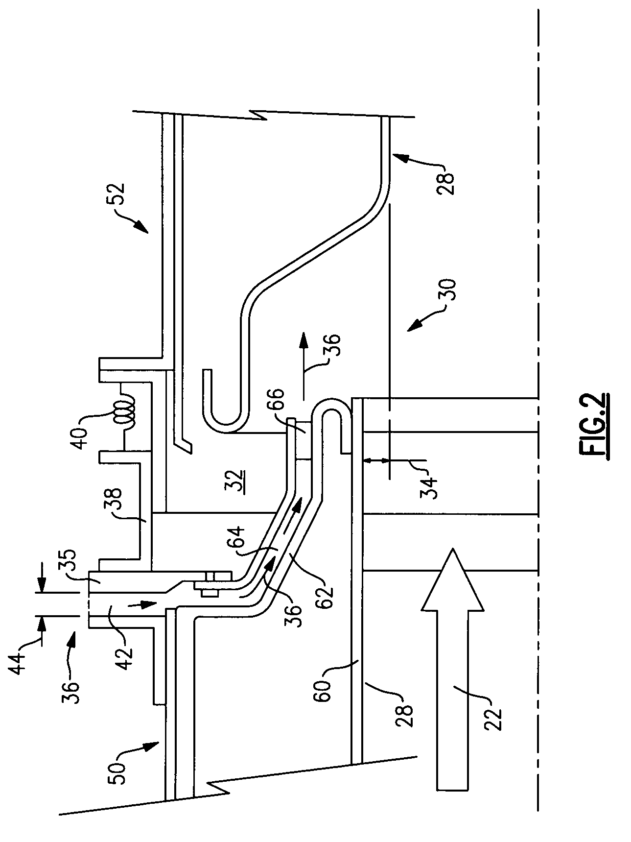
[0020]Hot core exhaust gas is exhausted through an exhaust duct assembly, schematically indicated at 12. The example exhaust duct assembly 12 includes a liner assembly 24 that defines an inner surface of the exhaust duct assembly. The example exhaust duct assembly 12 includes a first portion 50 and a second portion 52 that is movable relat...


PUM


Abstract

An exhaust liner assembly including an interface between moveable parts includes a seal liner having a plurality of slots. The size of each slot varies with the circumferential position of the liner assembly to provide a stable cavity pressure within the interface to create a stable barrier about the entire circumference of the exhaust liner assembly.

Description

[0001]This invention was made with government support under Contract No. N00019-02-C-3003 with the United States Navy. The government therefore has certain rights in this invention.BACKGROUND OF THE INVENTION[0002]This invention generally relates to an interface between liner components. More particularly, this invention relates to a device for introducing air into an interface between liner components.[0003]An exhaust liner assembly for a gas turbine engine includes liner components that shield engine and other components from hot core exhaust gases. Liner assemblies include features to accommodate thermal growth, provide desired aerodynamic properties as well as address other desired performance parameters. These considerations and features can be counter to the main purpose of the liner of isolating the extreme temperatures of the hot core gases from other engine components. For this reason, conventional liner assemblies utilize by-pass air in specific areas of the liner particul...

Claims


Application Information

Patent Timeline
Patent Type & Authority Patents(United States)
IPC IPC(8): F02K3/10
CPCF01D11/005F01D25/12F01D25/30F02K1/822Y02T50/675Y02T50/60
Inventor LAVIN, JEFFREY R.MURPHY, MICHAEL J.
Owner RTX CORP
Features
  • R&D
  • Intellectual Property
  • Life Sciences
  • Materials
  • Tech Scout
  • Unparalleled Data Quality
  • Higher Quality Content
  • 60% Fewer Hallucinations
Learn More